Welcome! Use the navigation to the left to view documents.
This manual provides information on the diagnosis, the service procedures, the adjustments, and the specifications for the Zero motorcycles.
Detailed descriptions of standard workshop procedures, safety principles and shop operations are not included. It is important to note that this manual contains a set of specific recommended service methods and that deviation from said methods could result in personal injury to service personnel or damage to equipment. Please understand that those methods could not possibly cover all conceivable ways in which service, whether or not recommended by Zero Motorcycles Inc., might be done or of the possibly hazardous consequences of each conceivable way, nor could Zero investigate all such ways. Anyone using service procedures or tools, whether or not recommended by Zero, must satisfy him or herself thoroughly that neither personal safety nor vehicle safety will be jeopardized by the service methods or tools selected.
The technicians who understand the material in this manual and in the appropriate Dealer Service Bulletins better, serve the motorcycle owners.
U.S. Manufacture:
Zero Motorcycles
380 El Pueblo Road
Scotts Valley, CA 95066
All information, illustrations and specifications contained in this Service Manual are based on the latest product information available. Zero reserves the right to make changes at any time, without notice, in colors, materials, equipment, specifications and models.
Zero may, subject to legal requirements, determine the Model Year designations of its vehicles. The Model Year designation on any particular model may be longer or shorter than 12 months.
Some vehicles pictured may contain non-U.S. equipment. Some models may be shown with optional equipment.
While Zero Motorcycles makes all reasonable efforts to provide accurate information in this Service Manual, there is no guarantee or warranty of accuracy. Furthermore, we do not assume any liability for the accuracy of completeness of information presented.
This Service Manual shall not be used or relied upon as a substitute for information that is available from your Zero Motorcycles dealer. Further information can be obtained from your authorized Zero dealer or Zeromotorcycles.com.
©2019 Zero Motorcycles Inc. Not to be reproduced wholly or in part without written permission of Zero Motorcycles Inc. The Zero Motorcycles name, model names and logo are registered trademarks.
Published by:
Zero Motorcycles Inc.
380 El Pueblo Road
Scotts Valley, CA 95066
www.zeromotorcycles.com
Dealer Service Portal
www.zeroserviceportal.com
ALL RIGHTS RESERVED
No part of this manual may be reproduced, stored in any retrieval system, or transmitted in any form or by any means including, but not limited to, electronic, mechanical, photocopying, and recording without the prior written permission of Zero Motorcycles Inc. This applies to all text, illustrations, and tables.
Version 1
Cautions, Notices, and Important are elements designed to prevent hazards; however, not all hazards can be foreseen. This information is placed at strategic locations within the service manual.
Caution: is used for the technician to take necessary action or not to take a prohibited action. Cautions are used to help prevent bodily injury to the technician or to the owner if the motorcycle was improperly repaired.
Notice: is used to call special attention to a necessary action or to a prohibited action. Notices are used to prevent damage to the motorcycle or prevent unnecessary repairs.
Important: is used to provide additional information or to clarify a procedure.

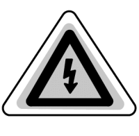
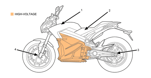
This symbol is located in various locations on the motorcycle to inform you that exposure to high voltage can cause shock, burns, and even death. The high voltage components on the motorcycle should be serviced by technicians with special training.
High voltage cable or wiring has an orange covering. Do not probe, tamper with, cut, or modify high voltage cable or wiring.
This manual covers the following motorcycles:
• Zero S: Street
- Cast Wheels
- Street Tires
• Zero SR: Street - Max Performance
- Cast Wheels
- Street Tires
• Zero DS: Dual Sport
- Cast Wheels (19-inch diameter front)
- Dual Sport Tires
• Zero DSR: Dual Sport - Max Performance
- Cast Wheels (19-inch diameter front)
- Dual Sport Tires
Version 1
Caution: Brake fluid may irritate eyes and skin. In case of contact, take the following actions:
• Eye Contact-rinse thoroughly with water
• Skin Contact-wash with soap and water
• If Ingested-contact a physician immediately
Version 1
Caution: Approved safety glasses and gloves should be worn when performing this procedure to reduce the chance of personal injury.
Version 1
Caution: Road test a motorcycle under safe conditions and while obeying all traffic laws. Do not attempt any maneuvers that could jeopardize the motorcycles control. Failure to adhere to these precautions could lead to serious personal injury and motorcycle damage.
Version 1
Notice: Avoid spilling brake fluid onto painted or other surfaces, electrical connections, wiring, or cables. Brake fluid will damage painted or other surfaces and cause corrosion to electrical components. If any brake fluid comes in contact with painted surfaces, immediately flush the area with water. If any brake fluid comes in contact with electrical connections, wiring, or cables, use a clean shop cloth to wipe away the fluid.
Version 1
Notice: Replacement fasteners must be the correct part number for that application. Use the correct fastener in the correct location. Fasteners requiring the use of thread-locking compound are specified in the repair procedure; refer to the product manufacture for proper usage. Always use new lock nuts, lock washers and cotter pins. Do not use paints, lubricants, or corrosion inhibitors on fasteners or fastener contact surfaces unless specified in the procedure. Coatings affect fastener torque and joint clamping force and may damage the fastener.
Version 1
Caution: Always perform the High Voltage Discharging procedure prior to servicing any High Voltage component or connection. Proper procedures must be followed.
Failure to follow the procedures may result in serious injury or death.
• Always verify that the high voltage has been disabled before working on or around high voltage components, wires, cables, or harnesses.
• Remove all metal objects such as rings and watches.
• Always tighten the high voltage terminal fasteners to the specified torque. Insufficient or excessive torque will cause malfunctions or damage.
• After finishing work on the high voltage system and before turning the key ON.
• Verify high voltage system integrity and that all connectors and covers are installed.
• Verify that all tools or loose components have been removed.
Caution: Exposure to high voltage can cause shock, burns, and even death. The high voltage components on the motorcycle should only be serviced by technicians familiar with the circuit/system operation. Refer to System Description and Operation.
High voltage components are identified by labels. Do not remove, open, take apart, or modify these components. High voltage cable or wiring has orange covering. Do not probe, tamper with, cut, or modify high voltage cable or wiring.
Version 1
|
Description
|
ZF7.2
|
ZF7.2 + POWER TANK
|
ZF14.4
|
ZF14.4 + POWER TANK
|
|
Range
|
||||
|
City
|
89 miles (143 km)
|
133 miles (214 km)
|
179 miles (288 km)
|
223 miles (359 km)
|
|
Highway, 55 mph Constant Speed
|
54 miles (87 km/h)
|
81 miles (130 km)
|
109 miles (175 km)
|
136 miles (219 k)
|
|
City/Highway, 55 mph Combined
|
68 miles (109 km)
|
101 miles (163 km)
|
135 miles (217 km)
|
169 miles (272 km)
|
|
Highway, 70 mph Constant Speed
|
45 miles (72 km)
|
67 miles (108 km)
|
90 miles (145 km)
|
112 miles (180 km)
|
|
City/Highway, 70 mph Combined
|
60 miles (97 km)
|
89 miles (143 km)
|
120 miles (193 km)
|
150 mph (241 km)
|
|
Motor
|
||||
|
Estimated Top Speed (max)
|
98 mph (158 km/h)
|
98 mph (158 km/h)
|
98 mph (158 km/h)
|
98 mph (158 km/h)
|
|
Estimated Top Speed (sustained)
|
80 mph (129 km/h)
|
80 mph (129 km/h)
|
85 mph (137 km/h)
|
85 mph (137 km/h)
|
|
Type
|
Z-Force® 75-5 passively air-cooled, high efficiency, radial flux permanent magnet, brushless motor
|
Z-Force® 75-7 passively air-cooled, high efficiency, radial flux permanent magnet, brushless motor
|
Z-Force® 75-7 passively air-cooled, high efficiency, radial flux permanent magnet, brushless motor
|
Z-Force® 75-7 passively air-cooled, high efficiency, radial flux permanent magnet, brushless motor
|
|
Controller
|
High efficiency, 550 amp, 3-phase brushless controller with regenerative deceleration
|
High efficiency, 550 amp, 3-phase brushless controller with regenerative deceleration
|
High efficiency, 550 amp, 3-phase brushless controller with regenerative deceleration
|
High efficiency, 550 amp, 3-phase brushless controller with regenerative deceleration
|
|
Power System
|
||||
|
Nominal Voltage
|
102.2 volts
|
102.2 volts
|
102.2 volts
|
102.2 volts
|
|
Power pack
|
Z-Force® Li-Ion intelligent
|
Z-Force® Li-Ion intelligent
|
Z-Force® Li-Ion intelligent
|
Z-Force® Li-Ion intelligent
|
|
Max capacity
|
7.2 kWh
|
10.8 kWh
|
14.4 kWh
|
18.0 kWh
|
|
Nominal capacity
|
6.3 kWh
|
9.5 kWh
|
12.6 kWh
|
15.8 kWh
|
|
Charger type
|
1.3 kW, integrated
|
1.3 kW, integrated
|
1.3 kW, integrated
|
1.3 kW, integrated
|
|
Charger Input
|
Universal 100 - 240 V AC
|
Universal 100 - 240 V AC
|
Universal 100 - 240 V AC
|
Universal 100 - 240 V AC
|
|
Charge time (standard)
|
5.2 hours (100% charged) / 4.7 hours (95% charged)
|
7.5 hours (100% charged) / 7.0 hours (95% charged)
|
9.8 hours (100% charged) / 9.3 hours (95% charged)
|
12.1 hours (100% charged) / 11.6 hours (95% charged)
|
|
Zero Rapid Charge Time (with one accessory charger)
|
3.1 hours (100% charged) / 2.6 hours (95% charged)
|
4.4 hours (100% charged) / 3.9 hours (95% charged)
|
5.7 hours (100% charged) / 5.2 hours (95% charged)
|
7.0 hours (100% charged) / 6.5 hours (95% charged)
|
|
Zero Rapid Charge Time (with max accessory chargers)
|
1.6 hours (100% charged) / 1.1 hours (95% charged)
|
2.2 hours (100% charged) / 2.7 hours (95% charged)
|
2.8 hours (100% charged) / 2.3 hours (95% charged)
|
3.3 hours (100% charged) / 2.8 hours (95% charged)
|
|
6kW Charge-Tank Accessory Charge Time
|
1.5 hours (100% charged) / 1.0 hours (95% charged)
|
N/A
|
2.5 hours (100% charged) / 2.0 hours (95% charged)
|
N/A
|
|
Drivetrain
|
||||
|
Transmission
|
Clutchless direct drive
|
Clutchless direct drive
|
Clutchless direct drive
|
Clutchless direct drive
|
|
Final drive
|
Poly Chain® HTD® Carbon™ belt
|
Poly Chain® GT® Carbon™ belt
|
Poly Chain® HTD® Carbon™ belt
|
Poly Chain® GT® Carbon™ belt
|
|
Motor Sprocket Size (# of teeth)
|
18
|
18
|
20
|
20
|
|
Wheel Sprocket Size (# of teeth)
|
90
|
90
|
90
|
90
|
|
Chassis / Suspension / Brakes
|
||||
|
Front suspension
|
Showa 41 mm inverted, cartridge forks with adjustable spring preload, compression and rebound damping
|
Showa 41 mm inverted, cartridge forks with adjustable spring preload, compression and rebound damping
|
Showa 41 mm inverted, cartridge forks with adjustable spring preload, compression and rebound damping
|
Showa 41 mm inverted, cartridge forks with adjustable spring preload, compression and rebound damping
|
|
Rear suspension
|
Showa 40 mm piston, Piggy-back reservoir shock with adjustable spring preload, compression and rebound damping
|
Showa 40 mm piston, Piggy-back reservoir shock with adjustable spring preload, compression and rebound damping
|
Showa 40 mm piston, Piggy-back reservoir shock with adjustable spring preload, compression and rebound damping
|
Showa 40 mm piston, Piggy-back reservoir shock with adjustable spring preload, compression and rebound damping
|
|
Front suspension travel
|
6.25 in (159 mm)
|
6.25 in (159 mm)
|
6.25 in (159 mm)
|
6.25 in (159 mm)
|
|
Rear suspension travel
|
6.35 in (161 mm)
|
6.35 in (161 mm)
|
6.35 in (161 mm)
|
6.35 in (161 mm)
|
|
Front brakes
|
Bosch Gen 9 ABS, J-Juan Floating 2 asymmetric piston hydraulic caliper, 320x5 mm thick disc
|
Bosch Gen 9 ABS, J-Juan Floating 2 asymmetric piston hydraulic caliper, 320x5 mm thick disc
|
Bosch Gen 9 ABS, J-Juan Floating 2 asymmetric piston hydraulic caliper, 320x5 mm thick disc
|
Bosch Gen 9 ABS, J-Juan Floating 2 asymmetric piston hydraulic caliper, 320x5 mm thick disc
|
|
Rear brakes
|
Bosch Gen 9 ABS, J-Juan Floating 1 piston hydraulic caliper, 240x4.5 mm thick disc
|
Bosch Gen 9 ABS, J-Juan Floating 1 piston hydraulic caliper, 240x4.5 mm thick disc
|
Bosch Gen 9 ABS, J-Juan Floating 1 piston hydraulic caliper, 240x4.5 mm thick disc
|
Bosch Gen 9 ABS, J-Juan Floating 1 piston hydraulic caliper, 240x4.5 mm thick disc
|
|
Front tire
|
110/70-17
|
110/70-17
|
110/70-17
|
110/70-17
|
|
Rear tire
|
140/70-17
|
140/70-17
|
140/70-17
|
140/70-17
|
|
Front wheel
|
3.00x17
|
3.00x17
|
3.00x17
|
3.00x17
|
|
Rear wheel
|
3.50x17
|
3.50x17
|
3.50x17
|
3.50x17
|
|
Dimensions
|
||||
|
Wheel base
|
55.5 in (1,410 mm)
|
55.5 in (1,410 mm)
|
55.5 in (1,410 mm)
|
55.5 in (1,410 mm)
|
|
Seat height
|
31.8 in (807 mm)
|
31.8 in (807 mm)
|
31.8 in (807 mm)
|
31.8 in (807 mm)
|
|
Rake (1/3 suspension sag)
|
24.0°
|
24.0°
|
24.0°
|
24.0°
|
|
Trail (1/3 suspension sag)
|
3.2 in (80 mm)
|
3.2 in (80 mm)
|
3.2 in (80 mm)
|
3.2 in (80 mm)
|
|
Weight
|
||||
|
Curb weight
|
313 lb (142 kg)
|
408 lb (185 kg)
|
408 lb (185 kg)
|
452 lb (205 kg)
|
|
Carrying capacity
|
404 lb (183 kg)
|
285 lb (129 kg)
|
367 lb (166 kg)
|
323 lb (147 kg)
|
Version 1
|
Description
|
ZF14.4
|
ZF14.4 +POWER TANK
|
|
Range
|
||
|
City
|
179 miles (288 km)
|
223 miles (359 km)
|
|
Highway, 55 mph Constant Speed
|
109 miles (175 km)
|
136 miles (219 km)
|
|
City/Highway, 55 mph Combined
|
135 miles (217 km)
|
169 miles (272 km)
|
|
Highway, 70 mph Constant Speed
|
90 miles (145 km)
|
112 miles (180 km)
|
|
City/Highway, 70 mph Combined
|
120 miles (193 km)
|
150 miles (241 km)
|
|
Motor
|
||
|
Estimated Top Speed (max)
|
102 mph (164 km/h)
|
102 mph (164 km/h)
|
|
Estimated Top Speed (sustained)
|
95 mph (153 km/h)
|
95 mph (153 km/h)
|
|
Type
|
Z-Force® 75-7R passively air-cooled, high efficiency, radial flux, permanent high-temp magnet, brushless motor
|
Z-Force® 75-7R passively air-cooled, high efficiency, radial flux, permanent high-temp magnet, brushless motor
|
|
Controller
|
High efficiency, 775 amp, 3-phase brushless controller with regenerative deceleration
|
High efficiency, 775 amp, 3-phase brushless controller with regenerative deceleration
|
|
Power System
|
||
|
Nominal Voltage
|
102.2 volts
|
102.2 volts
|
|
Power pack
|
Z-Force® Li-Ion intelligent integrated
|
Z-Force® Li-Ion intelligent integrated
|
|
Max capacity
|
14.4 kWh
|
18.0 kWh
|
|
Nominal capacity
|
12.6 kWh
|
15.8 kWh
|
|
Charger type
|
1.3 kW, integrated
|
1.3 kW, integrated
|
|
Charger input
|
Universal 100 - 240 V AC
|
Universal 100 - 240 V AC
|
|
Charge time (standard)
|
9.8 hours (100% charged) / 9.3 hours (95% charged)
|
12.1 hours (100% charged) / 11.6 hours (95% charged)
|
|
Zero Rapid Charge Time (with one accessory charger)
|
5.7 hours (100% charged) / 5.2 hours (95% charged)
|
7.0 hours (100% charged) / 6.5 hours (95% charged)
|
|
Zero Rapid Charge Time (with max accessory chargers)
|
2.8 hours (100% charged) / 2.3 hours (95% charged)
|
3.3 hours (100% charged) / 2.8 hours (95% charged)
|
|
6kW Charge-Tank Accessory Charge Time
|
2.5 hours (100% charged) / 2.0 hours (95% charged)
|
N/A
|
|
Drivetrain
|
||
|
Transmission
|
Clutchless direct drive
|
Clutchless direct drive
|
|
Final drive
|
Poly Chain® HTD® Carbon™ belt
|
Poly Chain® HTD® Carbon™ belt
|
|
Motor Sprocket Size (# of teeth)
|
20
|
20
|
|
Wheel Sprocket Size (# of teeth)
|
90
|
90
|
|
Chassis / Suspension / Brakes
|
||
|
Front suspension
|
Showa 41 mm inverted, cartridge forks with adjustable spring preload, compression and rebound damping
|
Showa 41 mm inverted, cartridge forks with adjustable spring preload, compression and rebound damping
|
|
Rear suspension
|
Showa 40 mm piston, Piggy-back reservoir shock with adjustable spring preload, compression and rebound damping
|
Showa 40 mm piston, Piggy-back reservoir shock with adjustable spring preload, compression and rebound damping
|
|
Front suspension travel
|
6.25 in (159 mm)
|
6.25 in (159 mm)
|
|
Rear suspension travel
|
6.35 in (161 mm)
|
6.35 in (161 mm)
|
|
Front brakes
|
Bosch Gen 9 ABS, J-Juan Floating 2 piston hydraulic caliper, 320x5 mm thick disc
|
Bosch Gen 9 ABS, J-Juan Floating 2 piston hydraulic caliper, 320x5 mm thick disc
|
|
Rear brakes
|
Bosch Gen 9 ABS, J-Juan Floating 1 piston hydraulic caliper, 240x4.5 mm thick disc
|
Bosch Gen 9 ABS, J-Juan Floating 1 piston hydraulic caliper, 240x4.5 mm thick disc
|
|
Front tire
|
110/70-17
|
110/70-17
|
|
Rear tire
|
140/70-17
|
140/70-17
|
|
Front wheel
|
3.00x17
|
3.00x17
|
|
Rear wheel
|
3.50x17
|
3.50x17
|
|
Dimensions
|
||
|
Wheel base
|
55.5 in (1,410 mm)
|
55.5 in (1,410 mm)
|
|
Seat height
|
31.8 in (807 mm)
|
31.8 in (807 mm)
|
|
Rake (1/3 suspension sag)
|
24.0°
|
24.0°
|
|
Trail (1/3 suspension sag)
|
3.2 in (80 mm)
|
3.2 in (80 mm)
|
|
Weight
|
||
|
Curb weight
|
414 lb (188 kg)
|
458 lb (208 kg)
|
|
Carrying capacity
|
361 lb (164 kg)
|
317 lb (144 kg)
|
Version 1
|
Description
|
ZF7.2
|
ZF7.2 + POWER TANK
|
ZF14.4
|
ZF14.4 + POWER TANK
|
|
Range
|
||||
|
City
|
82 miles (132 km)
|
121 miles (195 km)
|
163 miles (262 km)
|
204 miles (328 km)
|
|
Highway, 55 mph Constant Speed
|
49 miles (79 km)
|
73 miles (117 km)
|
98 miles (158 km)
|
122 miles (196 km)
|
|
City/Highway, 55 mph Combined
|
61 miles (98 km)
|
91 miles (146 km)
|
122 miles (196 km)
|
153 miles (246 km)
|
|
Highway, 70 mph Constant Speed
|
39 miles (63 km)
|
58 miles (93 km)
|
78 miles (126 km)
|
97 miles (156 km)
|
|
City/Highway, 70 mph Combined
|
53 miles (85 km)
|
78 miles (126 km)
|
105 miles (169 km)
|
132 miles (212 km)
|
|
Motor
|
||||
|
Estimated Top Speed (max)
|
98 mph (158 km/h)
|
98 mph (158 km/h)
|
98 mph (158 km/h)
|
98 mph (158 km/h)
|
|
Estimated Top Speed (sustained)
|
80 mph (129 km/h)
|
80 mph (129 km/h)
|
85 mph (137 km/h)
|
85 mph (137 km/h)
|
|
Type
|
Z-Force® 75-5 passively air-cooled, high efficiency, radial flux permanent magnet, brushless motor
|
Z-Force® 75-7 passively air-cooled, high efficiency, radial flux permanent magnet, brushless motor
|
Z-Force® 75-7 passively air-cooled, high efficiency, radial flux permanent magnet, brushless motor
|
Z-Force® 75-7 passively air-cooled, high efficiency, radial flux permanent magnet, brushless motor
|
|
Controller
|
High efficiency, 550 amp, 3-phase brushless controller with regenerative deceleration
|
High efficiency, 550 amp, 3-phase brushless controller with regenerative deceleration
|
High efficiency, 550 amp, 3-phase brushless controller with regenerative deceleration
|
High efficiency, 550 amp, 3-phase brushless controller with regenerative deceleration
|
|
Power System
|
||||
|
Power pack
|
Z-Force® Li-Ion intelligent
|
Z-Force® Li-Ion intelligent
|
Z-Force® Li-Ion intelligent
|
Z-Force® Li-Ion intelligent
|
|
Max capacity
|
7.2 kWh
|
10.8 kWh
|
14.4 kWh
|
18.0 kWh
|
|
Nominal capacity
|
6.3 kWh
|
9.5 kWh
|
12.6 kWh
|
15.8 kWh
|
|
Charger type
|
1.3 kW, integrated
|
1.3 kW, integrated
|
1.3 kW, integrated
|
1.3 kW, integrated
|
|
Charger input
|
Universal 100 - 240 V AC
|
Universal 100 - 240 V AC
|
Universal 100 - 240 V AC
|
Universal 100 - 240 V AC
|
|
Charge time (standard)
|
5.2 hours (100% charged) / 4.7 hours (95% charged)
|
7.5 hours (100% charged) / 7.0 hours (95% charged)
|
9.8 hours (100% charged) / 9.3 hours (95% charged)
|
12.1 hours (100% charged) / 11.6 hours (95% charged)
|
|
Zero Rapid Charge Time (with one accessory charger)
|
3.1 hours (100% charged) / 2.6 hours (95% charged)
|
4.4 hours (100% charged) / 3.9 hours (95% charged)
|
5.7 hours (100% charged) / 5.2 hours (95% charged)
|
7.0 hours (100% charged) / 6.5 hours (95% charged)
|
|
Zero Rapid Charge Time (with max accessory chargers)
|
1.6 hours (100% charged) / 1.1 hours (95% charged)
|
2.2 hours (100% charged) / 1.7 hours (95% charged)
|
2.8 hours (100% charged) / 2.3 hours (95% charged)
|
3.3 hours (100% charged) / 2.8 hours (95% charged)
|
|
6kW Charge-Tank Accessory Charge Time
|
1.5 hours (100% charged) / 1.0 hours (95% charged)
|
N/A
|
2.5 hours (100% charged) / 2.0 hours (95% charged)
|
N/A
|
|
Drivetrain
|
||||
|
Transmission
|
Clutchless direct drive
|
Clutchless direct drive
|
Clutchless direct drive
|
Clutchless direct drive
|
|
Final drive
|
Poly Chain® HTD® Carbon™ belt
|
Poly Chain® HTD® Carbon™ belt
|
Poly Chain® HTD® Carbon™ belt
|
Poly Chain® HTD® Carbon™ belt
|
|
Motor Sprocket Size (# of teeth)
|
18
|
18
|
20
|
20
|
|
Wheel Sprocket Size (# of teeth)
|
90
|
90
|
90
|
90
|
|
Chassis / Suspension / Brakes
|
||||
|
Front suspension
|
Showa 41 mm inverted, cartridge forks with adjustable spring preload, compression and rebound damping
|
Showa 41 mm inverted, cartridge forks with adjustable spring preload, compression and rebound damping
|
Showa 41 mm inverted, cartridge forks with adjustable spring preload, compression and rebound damping
|
Showa 41 mm inverted, cartridge forks with adjustable spring preload, compression and rebound damping
|
|
Rear suspension
|
Showa 40 mm piston, Piggy-back reservoir shock with adjustable spring preload, compression and rebound damping
|
Showa 40 mm piston, Piggy-back reservoir shock with adjustable spring preload, compression and rebound damping
|
Showa 40 mm piston, Piggy-back reservoir shock with adjustable spring preload, compression and rebound damping
|
Showa 40 mm piston, Piggy-back reservoir shock with adjustable spring preload, compression and rebound damping
|
|
Front suspension travel
|
7.00 in (178 mm)
|
7.00 in (178 mm)
|
7.00 in (178 mm)
|
7.00 in (178 mm)
|
|
Rear suspension travel
|
7.03 in (179 mm)
|
7.03 in (179 mm)
|
7.03 in (179 mm)
|
7.03 in (179 mm)
|
|
Front brakes
|
Bosch Gen 9 ABS, J-Juan Floating 2 piston hydraulic caliper, 320x5 mm thick disc
|
Bosch Gen 9 ABS, J-Juan Floating 2 piston hydraulic caliper, 320x5 mm thick disc
|
Bosch Gen 9 ABS, J-Juan Floating 2 piston hydraulic caliper, 320x5 mm thick disc
|
Bosch Gen 9 ABS, J-Juan Floating 2 piston hydraulic caliper, 320x5 mm thick disc
|
|
Rear brakes
|
Bosch Gen 9 ABS, J-Juan Floating 1 piston hydraulic caliper, 240x4.5 mm thick disc
|
Bosch Gen 9 ABS, J-Juan Floating 1 piston hydraulic caliper, 240x4.5 mm thick disc
|
Bosch Gen 9 ABS, J-Juan Floating 1 piston hydraulic caliper, 240x4.5 mm thick disc
|
Bosch Gen 9 ABS, J-Juan Floating 1 piston hydraulic caliper, 240x4.5 mm thick disc
|
|
Front tire
|
100/90-19
|
100/90-19
|
100/90-19
|
100/90-19
|
|
Rear tire
|
130/80-17
|
130/80-17
|
130/80-17
|
130/80-17
|
|
Front wheel
|
2.50x19
|
2.50x19
|
2.50x19
|
2.50x19
|
|
Rear wheel
|
3.50x17
|
3.50x17
|
3.50x17
|
3.50x17
|
|
Dimensions
|
||||
|
Wheel base
|
56.2 in (1,427 mm)
|
56.2 in (1,427 mm)
|
56.2 in (1,427 mm)
|
56.2 in (1,427 mm)
|
|
Seat height
|
33.2 in (843 mm)
|
33.2 in (843 mm)
|
33.2 in (843 mm)
|
33.2 in (843 mm)
|
|
Rake (1/3 suspension sag)
|
26.5°
|
26.5°
|
26.5°
|
26.5°
|
|
Trail (1/3 suspension sag)
|
4.6 in (117 mm)
|
4.6 in (117 mm)
|
4.6 in (117 mm)
|
4.6 in (117 mm)
|
|
Weight
|
||||
|
Curb weight
|
317 lb (144 kg)
|
362 lb (164 kg)
|
413 lb (187 kg)
|
457 lb (207 kg)
|
|
Carrying capacity
|
417 lb (189 kg)
|
372 lb (169 kg)
|
362 lb (164 kg)
|
318 lb (144 kg)
|
Version 1
|
Description
|
ZF14.4
|
ZF14.4 + POWER TANK
|
|
Range
|
||
|
City
|
163 miles (262 km)
|
204 miles (328 km)
|
|
Highway, 55 mph Constant Speed
|
98 miles (158 km)
|
122 miles (196 km)
|
|
City/Highway, 55 mph Combined
|
122 miles (196 km/h)
|
153 miles (246 km)
|
|
Highway, 70 mph Constant Speed
|
78 miles (126 km)
|
97 miles (156 km)
|
|
City/Highway, 70 mph Combined
|
105 miles (169 km)
|
132 miles (212 km)
|
|
Motor
|
||
|
Estimated Top Speed (max)
|
102 mph (164 km/h)
|
102 mph (164 km/h)
|
|
Estimated Top Speed (sustained)
|
90 mph (145 km/h)
|
90 mph (145 km/h)
|
|
Type
|
Z-Force® 75-7R passively air-cooled, high efficiency, radial flux, permanent high-temp magnet, brushless motor
|
Z-Force® 75-7R passively air-cooled, high efficiency, radial flux, permanent high-temp magnet, brushless motor
|
|
Controller
|
High efficiency, 775 amp, 3-phase brushless controller with regenerative deceleration
|
High efficiency, 775 amp, 3-phase brushless controller with regenerative deceleration
|
|
Power System
|
||
|
Nominal Voltage
|
102.2 volts
|
102.2 volts
|
|
Est. pack life to 80% (city)
|
220,000 miles (354,000 km)
|
N/A
|
|
Power pack
|
Z-Force® Li-Ion intelligent
|
Z-Force® Li-Ion intelligent
|
|
Max capacity
|
14.4 kWh
|
18.0 kWh
|
|
Nominal capacity
|
12.6 kWh
|
15.8 kWh
|
|
Charger type
|
1.3 kW, integrated
|
1.3 kW, integrated
|
|
Charger input
|
Universal 100 - 240 V AC
|
Universal 100 - 240 V AC
|
|
Charge time (standard)
|
9.8 hours (100% charged) / 9.3 hours (95% charged)
|
12.1 hours (100% charged) / 11.6 hours (95% charged)
|
|
Zero Rapid Charge Time (with one accessory charger)
|
5.7 hours (100% charged) / 5.2 hours (95% charged)
|
7.0 hours (100% charged) / 6.5 hours (95% charged)
|
|
Zero Rapid Charge Time (with max accessory chargers)
|
2.8 hours (100% charged) / 2.3 hours (95% charged)
|
3.3 hours (100% charged) / 2.8 hours (95% charged)
|
|
6kW Charge-Tank Accessory Charge Time
|
2.5 hours (100% charged) / 2.0 hours (95% charged)
|
N/A
|
|
Drivetrain
|
||
|
Transmission
|
Clutchless direct drive
|
Clutchless direct drive
|
|
Final drive
|
Poly Chain® HTD® Carbon™ belt
|
Poly Chain® HTD® Carbon™ belt
|
|
Motor Sprocket Size (# of teeth)
|
20
|
20
|
|
Wheel Sprocket Size (# of teeth)
|
90
|
90
|
|
Chassis / Suspension / Brakes
|
||
|
Front suspension
|
Showa 41 mm inverted, cartridge forks with adjustable spring preload, compression and rebound damping
|
Showa 41 mm inverted, cartridge forks with adjustable spring preload, compression and rebound damping
|
|
Rear suspension
|
Showa 40 mm piston, Piggy-back reservoir shock with adjustable spring preload, compression and rebound damping
|
Showa 40 mm piston, Piggy-back reservoir shock with adjustable spring preload, compression and rebound damping
|
|
Front suspension travel
|
7.00 in (178 mm)
|
7.00 in (178 mm)
|
|
Rear suspension travel
|
7.03 in (179 mm)
|
7.03 in (179 mm)
|
|
Front brakes
|
Bosch Gen 9 ABS, J-Juan Floating 2 piston hydraulic caliper, 320x5 mm thick disc
|
Bosch Gen 9 ABS, J-Juan Floating 2 piston hydraulic caliper, 320x5 mm thick disc
|
|
Rear brakes
|
Bosch Gen 9 ABS, J-Juan Floating 1 piston hydraulic caliper, 240x4.5 mm thick disc
|
Bosch Gen 9 ABS, J-Juan Floating 1 piston hydraulic caliper, 240x4.5 mm thick disc
|
|
Front tire
|
100/90-19
|
100/90-19
|
|
Rear tire
|
130/80-17
|
130/80-17
|
|
Front wheel
|
2.50x19
|
2.50x19
|
|
Rear wheel
|
3.50x17
|
3.50x17
|
|
Dimensions
|
||
|
Wheel base
|
56.2 in (1,427 mm)
|
56.2 in (1,427 mm)
|
|
Seat height
|
33.2 in (843 mm)
|
33.2 in (843 mm)
|
|
Rake (1/3 suspension sag)
|
26.5°
|
26.5°
|
|
Trail (1/3 suspension sag)
|
4.6 in (117 mm)
|
4.6 in (117 mm)
|
|
Weight
|
||
|
Curb weight
|
419 lb (190 kg)
|
463 lb (210 kg)
|
|
Carrying capacity
|
356 lb (161 kg)
|
312 lb (142 kg)
|
Version 1


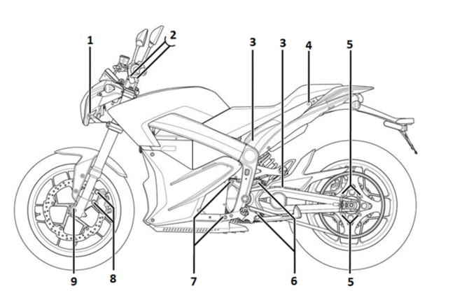
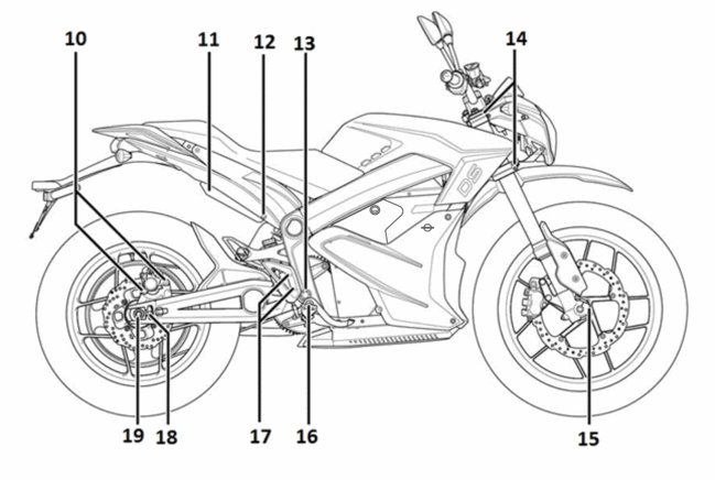
|
LOCATION
|
ITEM
|
TORQUE
|
NOTES
|
|
1
|
Headlight Bolts
|
11 N•m (8 lb ft)
|
Use LOCTITE® 242® (or equivalent)
|
|
2
|
Handlebar Clamp Bolts
|
26 N•m (19 lb ft)
|
-
|
|
3
|
Rear Shock Mount Bolts
|
54 N•m (40 lb ft)
|
-
|
|
4
|
Seat Bolts
|
22 N•m (16 lb ft)
|
-
|
|
5
|
Rear Sprocket to Wheel Bolts
|
35 N•m (26 lb ft)
|
Use LOCTITE® 242® (or equivalent)
|
|
6
|
Left Rear Motor Mount Bolts*
Right Rear Motor Mount Bolts |
27 N•m (20 lb ft)
27 N•m (20 lb ft) |
*Polylube 1000TM
|
|
7
|
Left Front Motor Mount Bolts*
Right Front Motor Mount Bolts |
27 N•m (20 lb ft)
27 N•m (20 lb ft) |
*Polylube 1000TM
|
|
8
|
Front Caliper Bolts
|
26 N•m (19 lb ft)
|
Use LOCTITE® 242® (or equivalent)
|
|
9
|
Front Axle
|
54 N•m (40 lb ft)
|
Use LOCTITE® anti-seize lubricant (or equivalent)
|
|
10
|
Rear Brake Caliper Slide Bolts
|
46 N•m (34 lb ft)
|
Use LOCTITE® 242® (or equivalent)
|
|
11
|
Rear Brushless Motor Controller Heat Sink to Frame Bolts
|
26 N•m (19 lb ft)
|
-
|
|
12
|
Front Brushless Motor Controller Heat Sink to Frame Bolts
|
26 N•m (19 lb ft)
|
-
|
|
13
|
Swingarm Pivot Bolt
|
102 N•m (75 lb ft)
|
-
|
|
14
|
Upper Triple Clamp Pinch Bolts
|
20 N•m (15 lb ft)
|
Use LOCTITE® 242® (or equivalent)
|
|
14
|
Lower Triple Clamp Pinch Bolts
|
23 N•m (17 lb ft)
|
Use LOCTITE® 242® (or equivalent)
|
|
15
|
Front Axle Pinch Bolts
|
22 N•m (16 lb ft)
|
Use LOCTITE® 242® (or equivalent)
|
|
16
|
Rear Brake Pedal Pivot Bolts
|
46 N•m (34 lb ft)
|
Use LOCTITE® 242® (or equivalent)
|
|
17
|
Rear brake Master Cylinder Guard Bolts
|
12 N•m (9 lb ft)
|
Use LOCTITE® 242® (or equivalent)
|
|
18
|
Rear Axle Slider Jam Nuts
|
26 N•m (19 lb ft)
|
-
|
|
19
|
Rear Axle Nut
|
102 N•m (75 lb ft)
|
Use LOCTITE® 242® (or equivalent)
|
Version 1
Whenever there is an excessive amount of current flowing through a circuit, the fusible element will melt and create an open or incomplete circuit. Fuses are a one-time protection device and must be replaced each time the circuit is overloaded. Replace the fuse with one of equal current and voltage rating. If the fuse melts repeatedly, inspect the circuit for an overload or short.
Fuse Center Location
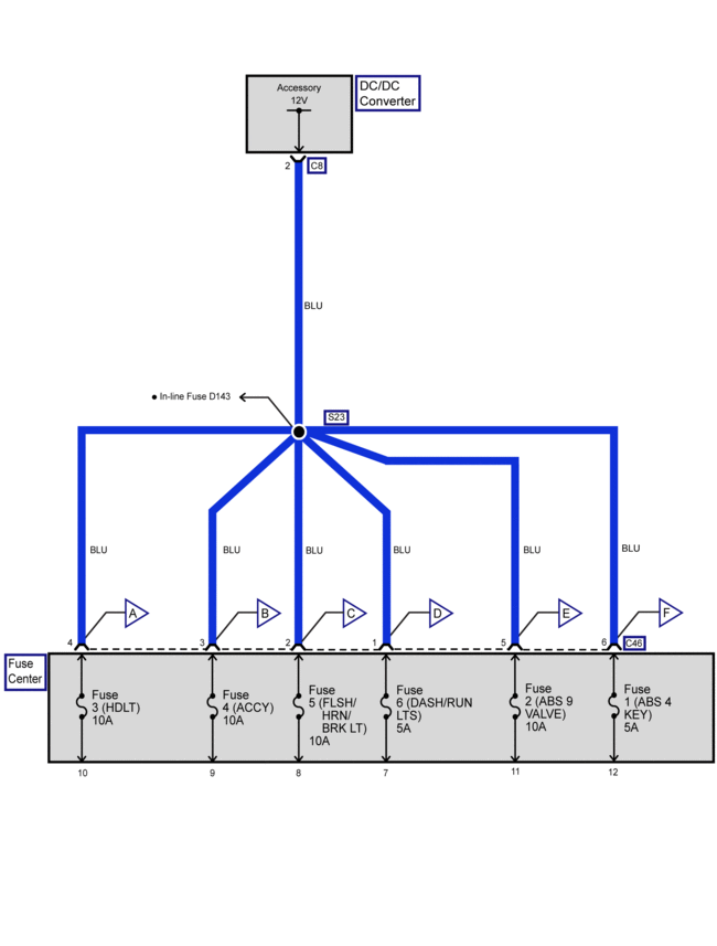
The 12-volt fuse center is located on the left side of the frame under the seat. Remove the seat to gain access to the 12 volt fuse center.

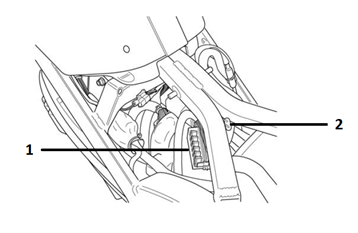
Legend:
1. Fuse Center
2. ABS 12 Volt Fuse
Fuses
|
Fuse
|
Rating
|
Circuits Controlled
|
|
1
|
5 A
|
ABS-4 Key
|
|
2
|
10 A
|
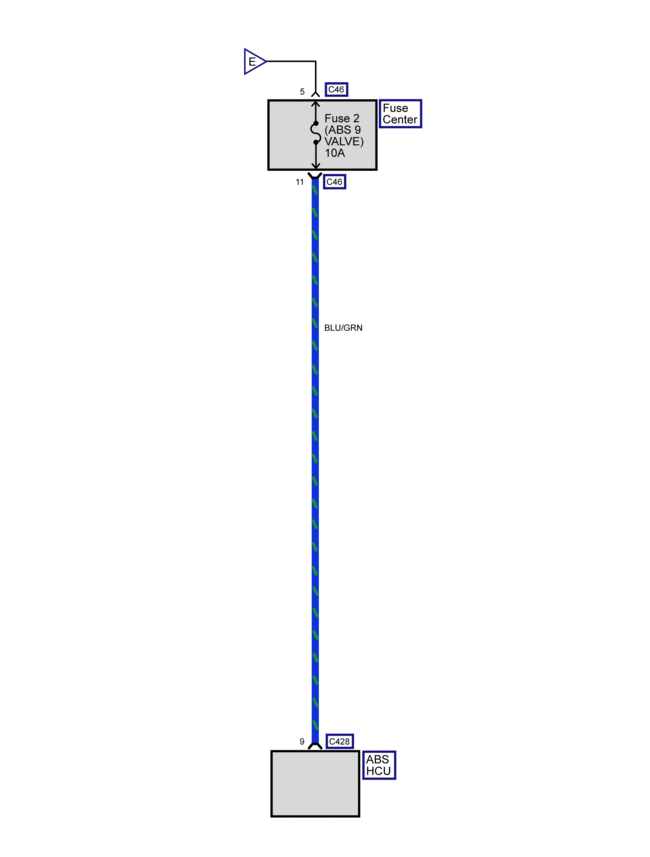
ABS-9 Valve
|
|
3
|
10 A
|
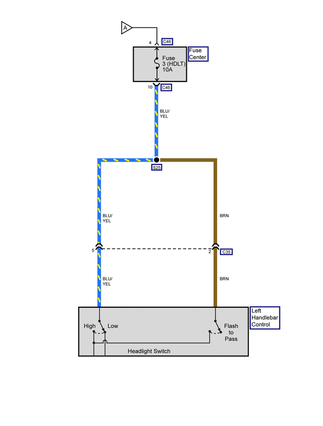
Headlight
|
|
4
|
10 A
|
Accessory
|
|
5
|
10 A
|
Flash to Pass Lights, Turn Signals, Horn, Brake/Tail Light
|
|
6
|
5 A
|
Dash, Running Lights
|
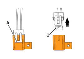
ABS 12 Volt Fuse

|
Fuse
|
Rating
|
Circuits Controlled
|
|
1
|
25 A
|
ABS-18 Motor
|
High Voltage Fuses
Power Pack
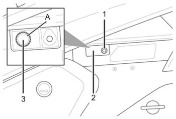
To access the ZF7.2 power pack fuse:
1. Remove the bolt (1) securing the fuse cover.
2. Remove the fuse cover (2) to access the fuse.
3. Unscrew the fuse's cover (3).
4. Replace the fuse (A).
5. Screw on the fuse's cover and install the fuse main cover. Torque the bolt to 1.3 N•m (11.5 lb in).

|
Fuse
|
Rating
|
Circuits Controlled
|
|
A
|
T3. 15 A Slow Blow
|
Low Power B+
|
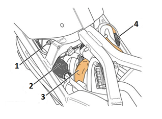
To access the ZF14.4 power pack fuse:
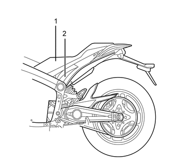
1. Remove the two bolts securing the seat to the motorcycle frame.
2. Pull the seat rearward to gain access to the fuses.
3. Unscrew the fuse’s cover.
4. Replace the fuse (1).

|
Fuse
|
Rating
|
Circuits Controlled
|
|
1
|
T3. 15 A Slow Blow
|
Low Power B+
|
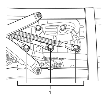
To access the high voltage fuses:
1. Remove the two bolts securing the seat to the motorcycle frame.
2. Pull the seat rearward to gain access to the fuses.
3. Pull back sheathing to access fuse holders (if necessary).
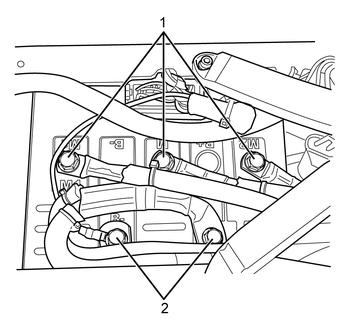
4. Unscrew the fuse’s cover (1, 2, and 3).
5. Replace the fuse.


|
Fuse
|
Rating
|
Circuits Controlled
|
|
1
|
SPT3 15 A
|
Low Power B+
|
|
2
|
ABC 4 A
|
Main Bike Board/Controller
|
|
3
|
ABC 4 A
|
DC/DC Converter
|
|
4
|
100 A
|
Charge Fuse (in-line)
|
These fuses can be checked by removing the fuse and checking for continuity. A fuse that has no continuity is considered to be melted.
Version 1
|
Part
|
Number
|
|
Headlight Bulb
|
H4 (55/60 watt)
|
|
Turn Signal Light Bulb (amber)
|
RY10W (10 watt)
|
|
Brake/Tail Light Bulb
|
LED (replace the entire unit)
|
|
Front Running Light Bulb
|
W3W (3 watt)
|
Version 1
Vehicle Identification Number (VIN)

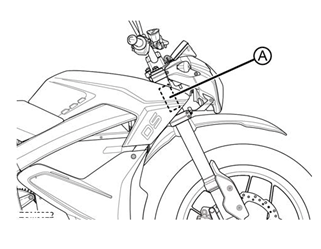
Legend:
A. VIN Number
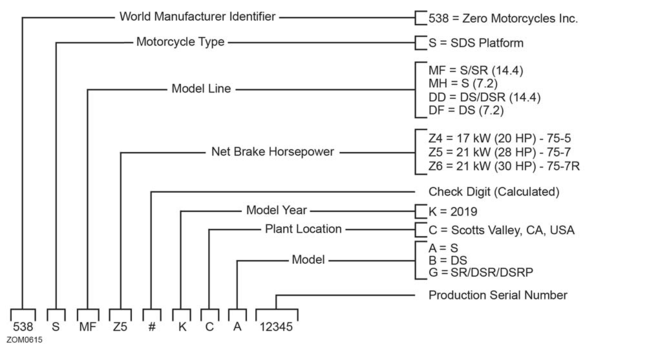
VIN Break Down
The VIN is a 17-digit number stamped on the head tube of the frame. Do not alter or remove this as it is the legal identifier for the motorcycle.

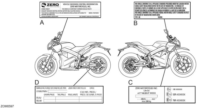
The vehicle could contain the following information for both North American and European models:

Legend:
A. VECI (Vehicle Emission Control Information) label
B. VIN label (North America) - certification label shown
C. VIN label (European Union) - certification label
D. Tire and loading information label
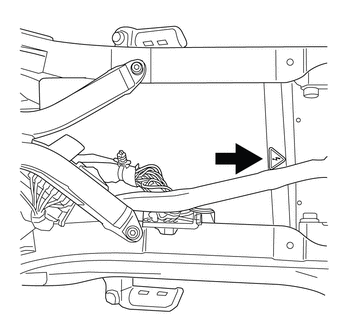
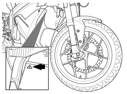
High Voltage Warning Label
Under the seat above the motor controller


Version 1
Important:
• Perform a thorough inspection of the entire motorcycle at every service interval. Replace any parts found to be worn or in need of replacement.
• Use only genuine Zero or Zero-recommended parts and lubricants/cleaners or their equivalent. Parts that do not meet Zero’s design specifications may damage the motorcycle and/or void the warranty.
|
No. |
ITEM |
ROUTINE |
EVERY RIDE |
INITIAL |
ODOMETER MILEAGE READINGS |
||||
|
1,000 km (600 mi) or 1 month |
7,000 km (4, 000 mi) or 6 months |
13,000 km (8,000 mi) or 12 months |
19,000 km (12,000 mi) or 18 months |
25,000 km (16,000 mi) or 24 months |
31,000 km (20,000 mi) or 30 months |
||||
|
1a |
Brake Fluid (front and rear) | Check Brake Fluid Level. Add as needed |
● |
● |
● |
● |
● |
● |
● |
|
1b |
Brake Fluid (front and rear) | Replace Brake Fluid (Every 12 months). |
● |
● |
|||||
|
2 |
Front Brake | • Check operation, and for fluid leakage. • Replace brake pads if necessary. |
● |
● |
● |
● |
● |
● |
● |
|
3 |
Rear Brake | • Check operation, and for fluid leakage. • Replace brake pads if necessary. |
● |
● |
● |
● |
● |
● |
● |
|
4 |
Wheels | • Check run-out and for damage. • Replace if necessary. |
|
● |
● |
● |
● |
● |
|
|
5 |
Tires | • Check tread depth and for damage. Replace if necessary. • Check air pressure. Correct if necessary. |
● |
|
● |
● |
● |
● |
● |
|
6 |
Wheel Bearings | • Check bearings for smooth operation. Replace if necessary. | ● |
● |
● |
● |
● |
● |
|
|
7 |
Drive Belt |
• Check belt slack and condition. • Check for cracking and/or replace the belt every 37,000 km (24,000 mi) |
● |
● |
|||||
|
8 |
Steering Bearings | Check assembly for looseness. |
● |
● |
● |
● |
Repack |
● |
|
|
9 |
Chassis Fasteners | • Check all chassis fittings and fasteners. Tighten and adjust as needed. |
● |
● |
● |
● |
● |
||
|
10 |
Front Brake Lever Pivot Shaft | • Apply silicon grease lightly. • Check operation. • Service/Rebuild if necessary. |
● |
● |
● |
● |
● |
● |
|
|
11 |
Front Fork | • Check operation and for oil leakage. • Service/rebuild if necessary. |
● |
|
● |
● |
● |
● |
● |
|
12 |
Rear Shock Absorber Assembly | • Check operation and for oil leakage. Replace if necessary. |
● |
|
● |
● |
● |
● |
● |
|
13 |
Throttle Grip | • Check operation and free play. |
● |
|
● |
● |
● |
● |
● |
|
14 |
Kickstand Pivots | • Check operation. • Apply silicon grease lightly. |
● |
● |
● |
● |
● |
||
|
15 |
Kickstand Switch | Check operation and replace if necessary. |
● |
● |
● |
● |
● |
● | |
|
16 |
Drive Motor | Commissioning and timing |
|
● |
|
● |
|
● |
|
Version 1
Caution: Refer to Road Test Caution in General Information.
Caution: Road test a motorcycle under safe conditions and while obeying all traffic laws. Do not attempt any maneuvers that could jeopardize the control of the motorcycle. Failure to adhere to these precautions could lead to serious personal injury and motorcycle damage.
Before the road test, ensure the following:
• The exterior lighting is working correctly.
• Tire pressure is correct.
During the road test:
• Perform the test only when traffic conditions permit.
• Operate the motorcycle in a controlled, safe manner.
• Observe all traffic regulations.
• Observe any unusual vibrations.
o When braking
o When coasting
o When accelerating
o When regen braking
• Observe any unusual sounds.
o When braking
o When coasting
o When accelerating
o When regen braking
Choose different road surfaces when test driving to verify that the condition is not related to road surfaces. Observe where the problem condition is located: Front, back or under the motorcycle. If the condition is something that is heard or felt, driving a similarly equipped motorcycle may determine if the issue is an operating characteristic of the motorcycle.
Version 1
Use only Zero specified tools when servicing the motorcycle. The motorcycle contains a mix of metric and standard fasteners. Use of the incorrect tool or fastener may damage the motorcycle.
All dealers should have the following:
Special Tools:
• PN 85-05665 Controller Discharge Tool

Basic Tools:
• Safety glasses
• Spring loaded center punch
• 3 mm, 4 mm, 5 mm, 6 mm, 8 mm and 10 mm "T", "L", and socket hex wrenches
• Zip tie pulling/cutting gun
• Rubber dead blow hammer
• Punch
• Flat and rat tail file
• Gear Puller (motor sprocket)
• T25 Star socket
• T15 tamperproof star socket
• 8 mm, 10 mm, 13 mm, 14 mm, 15 mm, 17 mm, 22 mm and 27 mm combo wrench
• Phillips and Flat head screw drivers
• 1/4" drive 1", 2”, and 3” socket extension
• 3/8" drive 1", 2", and 3" socket extension
• Needle nose pliers
• Adjustable pin spanner wrench
• 1/4" and 3/8" drive 8mm, 10mm and 13mm socket
• 1/4" and 3/8" drive socket wrench
• Bicycle type headset press and removal tool
• Motorcycle head bearing press and removal tool
• Belt Tension Tester
• External snap ring pliers
Equipment:
• Tire levers and or a tire changing machine
• Motorcycle stand/lift
Version 1
CAUTION: Under-inflation is the most
common cause of tire failure and may result in severe tire cracking,
tread separation, “blowout,” or unexpected loss of motorcycle control
causing personal injury and possible death.
The tire pressure is checked using an accurate gauge when the tires are
cold. This means that the tires have not been ridden on for 3 hours.
Always replace the valve stem cap when finished.
|
MODEL
|
FRONT
|
REAR
|
|
S
|
221 kpa (32 psi)
|
234 kpa (34 psi)
|
|
DS
|
221 kpa (32 psi)
|
234 kpa (34 psi)
|
|
SR |
221 kpa (32 psi)
|
234 kpa (34 psi) |
|
DSR
|
221 kpa (32 psi)
|
234 kpa (34 psi)
|
Version 1
Zero Motorcycles Inc. can be contacted via the contact methods listed below. Please have available the following, as it is essential to effectively and efficiently answer your questions or resolve your concerns.
• Owner’s name and address
• Owner’s telephone number
• Vehicle identification number (VIN)
• Date of purchase
• Power Pack serial number
• Motor serial number
An owner information chart is provided in the Zero Motorcycles Owner's Manual to record this information.
North American and Canada:
Zero Motorcycles
380 El Pueblo Rd.
Scotts Valley, California 95066
USA
Phone: (888) 786-9376
Monday-Friday
8am to 5pm Pacific Time
E-mail: service@zeromotorcycles.com
24 hours
International Contacts:
For the most up to date information, please refer to http://www.zeromotorcycles.com/contact
Version 1
Important: Using the following steps of the vibration diagnostic process will help you to effectively narrow-down and pin-point the search for the specific source of a vibration concern and to arrive at an accurate repair.
Vibration Diagnostic Process
1. Gather specific information on the customer's vibration concern.
2. Perform the road testing steps in sequence as identified in Road Testing Procedure in order to duplicate the customer's concern and evaluate the symptoms of the concern under changing conditions. Observe what the vibration feels like and what it sounds like. Observe when the symptoms first appear, when they change, and when they cease.
3. Determine if the customer's vibration concern is truly an abnormal condition or something that is potentially an operating characteristic of the motorcycle.
4. Systematically eliminate or 'rule-out' possible motorcycle systems.
5. Focus diagnostic efforts on the remaining motorcycle system and systematically eliminate or "rule-out" possible components of that system.
6. Make a repair on the remaining component, or components, which have not been eliminated systematically, and must therefore be the cause of the vibration.
7. Verify that the customer's concern has been eliminated or at least brought to an acceptable level.
8. Again perform the road testing steps in sequence in order to verify that the vehicle did not have more than one vibration occurring.
Preliminary Visual/Physical Inspection
• Inspect for aftermarket equipment and modifications, which could affect the operation of the motorcycles rotating component systems.
• Inspect the easily accessible or visible components of the motorcycles rotating component systems for obvious damage or conditions, which could cause the symptom.
• Inspect the tire inflation pressures for the proper pressure.
Version 1
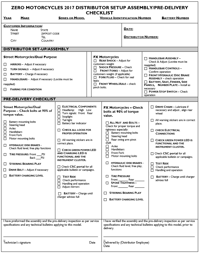
The latest version of the Pre-Delivery Inspection Checklist is available to your dealership through Zero Motorcycles Service Portal (Service.Zeromotorcycles.com) in the Dealer FAQ section.

Version 1
Although unpacking the Zero motorcycle can be done by a single person, it is recommended to have a second person to help lift and remove your motorcycle from the crate base.
Wood Shipping Crate
Outer Box Cover
• Cut and remove the two metal outer box retention straps.
• Remove the screws along the crate base.
• Remove screws along the side of the crate that has the metal clamps on it.
• Remove the metal clamps, and remove the side panel.
• Remove the remaining outer box cover.
Inner Assembly
• Carefully remove plastic cover from motorcycle.
• Locate small parts box below motorcycle and put to the side. (This box contains important documentation, owner’s manual, keys, handlebar clamps and hardware, etc.)
• Carefully lift rear portion of the motorcycle over the swingarm standoff and off crate base.
• Carefully lift front wheel out of crate base.
• Deploy kickstand, lean motorcycle and inspect in accordance with delivery inspection sheet.
Card Board Shipping Crate
Outer Box Cover
• Cut and remove the two plastic outer box retention straps.
• Unscrew stabilizer bar bolts, one on each side of outer box.
• Open box top and remove inner cardboard end reinforcement sleeves.
• Unscrew stabilizer bar from handlebar riser and remove.
• Unscrew lower crate cover retaining screws and washers.
• Lift or cut outer box away from motorcycle.
Inner Assembly
• Carefully remove plastic cover from motorcycle.
• Locate small parts box below motorcycle and put to the side. (This box contains important documentation, owner’s manual, keys, handlebar clamps and hardware, etc.)
• Remove the tie down straps from the crate base.
• Carefully lift rear portion of the motorcycle over the swingarm standoff and off crate base.
• Carefully lift front wheel out of crate base.
• Deploy kickstand, lean motorcycle and inspect in accordance with delivery inspection sheet.
Recycling
The Zero Motorcycles shipping crate and packaging materials were designed to be completely recycled. Please cut down and recycle all cardboard, plastic, and metal materials in appropriate receptacles.
The tie down straps that accompanied your motorcycle can be reused as regular tie down straps for transporting your motorcycle.
Version 1
Important: Using the following steps of the vibration diagnostic process will help you to effectively narrow-down and pin-point the search for the specific source of a vibration concern and to arrive at an accurate repair.
Vibration Diagnostic Process
1. Gather specific information on the customer's vibration concern.
2. Perform the road testing steps in sequence as identified in Road Testing Procedure in order to duplicate the customer's concern and evaluate the symptoms of the concern under changing conditions. Observe what the vibration feels like and what it sounds like. Observe when the symptoms first appear, when they change, and when they cease.
3. Determine if the customer's vibration concern is truly an abnormal condition or something that is potentially an operating characteristic of the motorcycle.
4. Systematically eliminate or 'rule-out' possible motorcycle systems.
5. Focus diagnostic efforts on the remaining motorcycle system and systematically eliminate or "rule-out" possible components of that system.
6. Make a repair on the remaining component, or components, which have not been eliminated systematically, and must therefore be the cause of the vibration.
7. Verify that the customer's concern has been eliminated or at least brought to an acceptable level.
8. Again perform the road testing steps in sequence in order to verify that the vehicle did not have more than one vibration occurring.
Preliminary Visual/Physical Inspection
• Inspect for aftermarket equipment and modifications, which could affect the operation of the motorcycles rotating component systems.
• Inspect the easily accessible or visible components of the motorcycles rotating component systems for obvious damage or conditions, which could cause the symptom.
• Inspect the tire inflation pressures for the proper pressure.
Version 1
The latest version of the Pre-Delivery Inspection Checklist is available to your dealership through Zero Motorcycles Service Portal (Service.Zeromotorcycles.com) in the Dealer FAQ section.


Version 1
Although unpacking the Zero motorcycle can be done by a single person, it is recommended to have a second person to help lift and remove your motorcycle from the crate base.
Wood Shipping Crate
Outer Box Cover
• Cut and remove the two metal outer box retention straps.
• Remove the screws along the crate base.
• Remove screws along the side of the crate that has the metal clamps on it.
• Remove the metal clamps, and remove the side panel.
• Remove the remaining outer box cover.
Inner Assembly
• Carefully remove plastic cover from motorcycle.
• Locate small parts box below motorcycle and put to the side. (This box contains important documentation, owner’s manual, keys, handlebar clamps and hardware, etc.)
• Carefully lift rear portion of the motorcycle over the swingarm standoff and off crate base.
• Carefully lift front wheel out of crate base.
• Deploy kickstand, lean motorcycle and inspect in accordance with delivery inspection sheet.
Card Board Shipping Crate
Outer Box Cover
• Cut and remove the two plastic outer box retention straps.
• Unscrew stabilizer bar bolts, one on each side of outer box.
• Open box top and remove inner cardboard end reinforcement sleeves.
• Unscrew stabilizer bar from handlebar riser and remove.
• Unscrew lower crate cover retaining screws and washers.
• Lift or cut outer box away from motorcycle.
Inner Assembly
• Carefully remove plastic cover from motorcycle.
• Locate small parts box below motorcycle and put to the side. (This box contains important documentation, owner’s manual, keys, handlebar clamps and hardware, etc.)
• Remove the tie down straps from the crate base.
• Carefully lift rear portion of the motorcycle over the swingarm standoff and off crate base.
• Carefully lift front wheel out of crate base.
• Deploy kickstand, lean motorcycle and inspect in accordance with delivery inspection sheet.
Recycling
The Zero Motorcycles shipping crate and packaging materials were designed to be completely recycled. Please cut down and recycle all cardboard, plastic, and metal materials in appropriate receptacles.
The tie down straps that accompanied your motorcycle can be reused as regular tie down straps for transporting your motorcycle.
Version 1
|
Application
|
Specification
|
|
|
Metric
|
English
|
|
|
Power Pack Bolts
|
27 N•m
|
20 lb ft
|
| Brake Pedal Pivot Bolt* | 46 N•m | 34 lb ft |
| Brushless Motor Controller Cable Bolt | 12 N•m | 9 lb ft |
| Seat Bolts | 22 N•m | 16 lb ft |
| Skid Plate Bolt | 9 N•m | 7 lb ft |
| Rear Tank Bolts | 5 N•m | 48 lb in |
| Front Fairing Screws | 2 N•m | 18 lb in |
| Front Fender Bolts DS | 3 N•m | 24 lb in |
| Front Fender Bolts S/SR/DSR | 11 N•m | 8 lb ft |
| Front Tank Bolts | 4 N•m | 35 lb in |
| Master Cylinder Guard Bolts* | 12 N•m | 9 lb ft |
| Instrument Panel Nuts | 4 N•m | 36 lb in |
| ABS Fuse Holder Bolts | 3 N•m | 26 lb in |
| Fuse Holder Bolts | 1 N•m | 12 lb in |
*Use LOCTITE® 242® (or equivalent)
Version 1

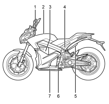
Legend:
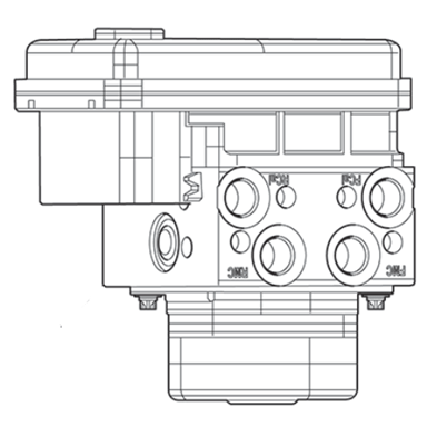
1. ABS HCU/Pump
2. Power Tank/Charge Tank (Optional)
3. Power Pack
4. DC/DC Converter, Fuse Center and Main Bike Board (MBB) (under seat)
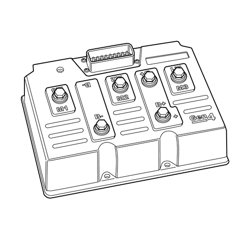
5. Brushless Motor Controller
6. Brushless Motor
7. Integrated Power Pack Charger
Version 1

Version 1
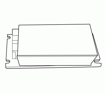
ZF14.4

ZF7.2

Version 1

Version 1
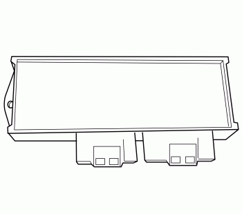
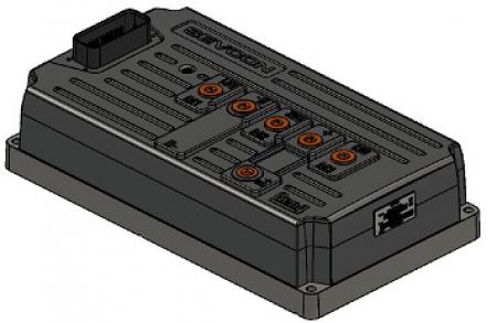
Size 4 Controller

Size 6 Controller

Version 1

Version 1
| SCH3443
Loading image...

|
Version 1
|
SCH3444
Loading image...

|
Version 1
|
SCH3445
Loading image...

|
Version 1
|
SCH3448
Loading image...

|
Version 1
|
SCH3449
Loading image...

|
Version 1
|
SCH3480
Loading image...

|
Version 1
|
SCH3450
Loading image...

|
Version 1
|
SCH3451
Loading image...

|
Version 1
|
SCH3452
Loading image...

|
Version 1
|
SCH2739
Loading image...

|
Version 1
|
SCH3480
Loading image...

|
Version 1
|
SCH3450
Loading image...

|
Version 1
|
SCH3451
Loading image...

|
Version 1
|
SCH3452
Loading image...

|
Version 1
|
SCH2739
Loading image...

|
Version 1
|
SCH3461
Loading image...

|
Version 1
|
SCH3459
Loading image...

|
Version 1
|
SCH3460
Loading image...

|
Version 1
|
SCH3455
Loading image...

|
Version 1
|
sch3468
Loading image...

|
Version 1
|
sch3469
Loading image...

|
Version 1
|
SCH3464
Loading image...

|
Version 1
|
SCH3465
Loading image...

|
Version 1
|
SCH3454
Loading image...

|
Version 1
|
SCH2718
Loading image...

|
Version 1
|
SCH2724
Loading image...

|
Version 1
|
SCH3474
Loading image...

|
Version 1
|
SCH3485
Loading image...

|
Version 1
|
SCH3802
Loading image...

|
Version 1
|
SCH2721
Loading image...

|
Version 1
|
sch2724
Loading image...

|
Version 1
|
SCH3490
Loading image...

|
Version 1
|
SCH3456
Loading image...

|
Version 1
|
SCH3457
Loading image...

|
Version 1
|
sch3470
Loading image...

|
Version 1
|
SCH3473
Loading image...

|
Version 1
|
SCH3457
Loading image...

|
Version 1
|
sch3470
Loading image...

|
Version 1
|
SCH3473
Loading image...

|
Version 1
|
sch3472
Loading image...

|
Version 1
|
SCH3466
Loading image...

|
Version 1
|
sch3473
Loading image...

|
Version 1
|
SCH3469
Loading image...

|
Version 1
|
SCH2751
Loading image...

|
Version 1
|
SCH2721
Loading image...

|
Version 1
|
SCH3466
Loading image...

|
Version 1
|
SCH3463
Loading image...

|
Version 1
|
SCH2719
Loading image...

|
Version 1
| SCH3443A
Loading image...

|
Version 1
|
SCH2727
Loading image...

|
Version 1
|
SCH3475
Loading image...

|
Version 1
|
SCH3479
Loading image...

|
Version 1
|
SCH3449A
Loading image...

|
Version 1
|
SCH3480A
Loading image...

|
Version 1
|
SCH3481
Loading image...

|
Version 1
|
SCH3451A
Loading image...

|
Version 1
|
sch3452A
Loading image...

|
Version 1
|
SCH2739A
Loading image...

|
Version 1
|
SCH3479
Loading image...

|
Version 1
|
SCH3449A
Loading image...

|
Version 1
|
SCH3480A
Loading image...

|
Version 1
|
SCH3481
Loading image...

|
Version 1
|
SCH3451A
Loading image...

|
Version 1
|
sch3452A
Loading image...

|
Version 1
|
SCH2739A
Loading image...

|
Version 1
|
SCH3491
Loading image...

|
Version 1
|
SCH3459A
Loading image...

|
Version 1
|
SCH3492
Loading image...

|
Version 1
|
SCH3455A
Loading image...

|
Version 1
|
sch3488
Loading image...

|
Version 1
|
sch3469A
Loading image...

|
Version 1
|
SCH3464A
Loading image...

|
Version 1
|
SCH3465A
Loading image...

|
Version 1
|
SCH3482
Loading image...

|
Version 1
|
SCH2718
Loading image...

|
Version 1
|
SCH3474A
Loading image...

|
Version 1
|
SCH3471
Loading image...

|
Version 1
|
SCH3802A
Loading image...

|
Version 1
|
SCH2721
Loading image...

|
Version 1
|
SCH3490A
Loading image...

|
Version 1
|
SCH3456A
Loading image...

|
Version 1
|
SCH3483
Loading image...

|
Version 1
|
sch3470A
Loading image...

|
Version 1
|
SCH3473A
Loading image...

|
Version 1
|
SCH3483
Loading image...

|
Version 1
|
sch3470A
Loading image...

|
Version 1
|
SCH3473A
Loading image...

|
Version 1
|
sch3486
Loading image...

|
Version 1
|
sch3487
Loading image...

|
Version 1
|
sch3473A
Loading image...

|
Version 1
|
SCH3463A
Loading image...

|
Version 1
|
SCH2719
Loading image...

|
Version 1
|
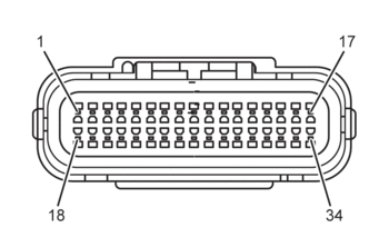
C1 Main Bike Board |
|||
|
18007
Version 1 21762
Version 2 |
|||
|
Connector Part Information |
|
||
|
Pin |
Wire Color |
Function |
|
| 1 | ORN/RED | Motor Controller Enable | |
| 1 | ORN/RED | Motor Controller Enable | |
| 2 | — | Not Used | |
| 3 | WHT/GRN | ABS HCU Voltage | |
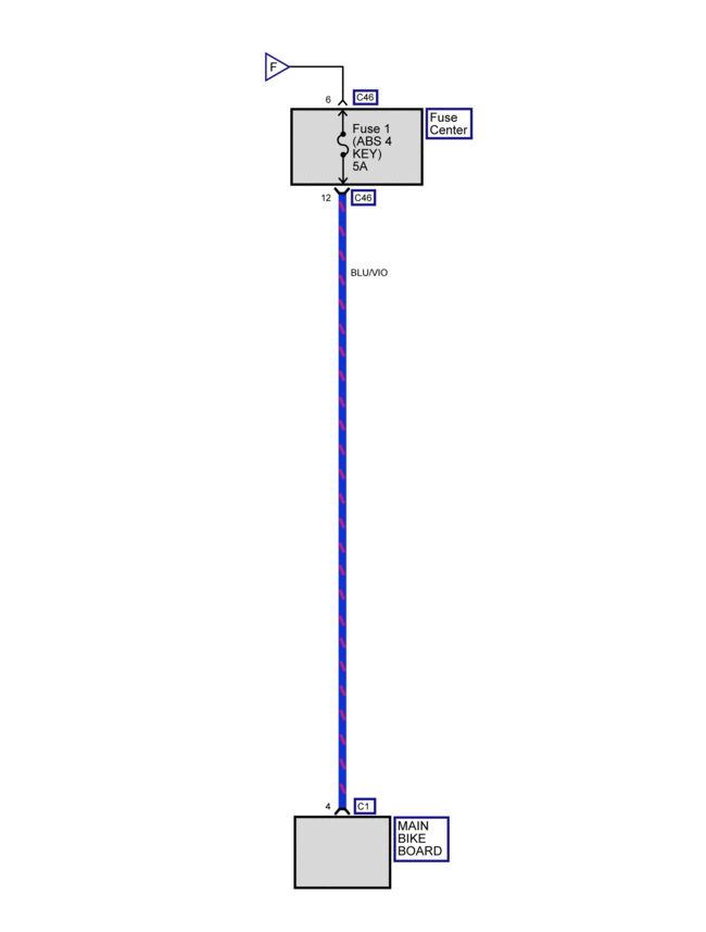
| 4 | BLU/VIO | Fuse 1 ABS 4 Key, 12 Volt Positive | |
| 5-6 | — | Not Used | |
| 7 | ORN/BLK | Power Pack Ground | |
| 8 | — | Not Used | |
| 9 | BRN/WHT | System ON Output | |
| 10 | — | Not Used | |
| 11 | YEL/BLK | Kickstand Switch Signal | |
| 12 | ORN/BLK | Kickstand Switch Ground | |
| 13 | WHT/BLU | Check Engine Light Control | |
| 14 | RED | Fuel Gauge 5V Reference | |
| 15 | YEL/GRN | Key ON 12V | |
| 16 | YEL | Temperature Warning Lamp Control | |
| 17 | YEL/BLK | Warning Lamp Control | |
| 18 | ORN/BRN | MBB Low Power | |
| 19 | ORN/GRY | Motor Controller Neutral | |
| 20 | ORN/RED | DC/DC Converter Enable | |
| 21 | — | Not Used | |
| 22 | BLK/WHT | Battery Throttle Enable | |
| 23 | RED | Ext Switch 5V | |
| 24 | RED/BLK | Motor Stop Switch IN | |
| 25-26 | — | Not Used | |
| 27 | RED | Kickstand Switch Signal 5V | |
| 28 | WHT/RED | Brake Switch Input | |
| 29 | BLK | 12 Volt Ground | |
| 30 | BLU/WHT | ABS Indicator Light Control | |
| 31 | ORN | Red Charge Indicator Light Control | |
| 32 | ORN/BLK | Instrument Cluster Light Ground | |
| 33 | VIO | Charge Indicator Control | |
| 34 | RED/WHT | Armed Indicator Light Control | |
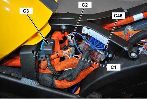
| Under the Seat Behind the Power Pack |
|
COM1978
Loading image...

|
Version 1
|
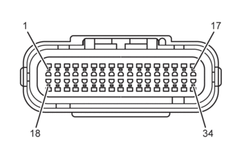
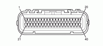
C2 Main Bike Board |
||
|
CON0765
|
||
|
Connector Part Information |
|
|
|
Pin |
Wire Color |
Function |
| 1 | ORN/BLK | Motor Controller Ground |
| 2 | YEL/RED | Motor Controller 24 Volt |
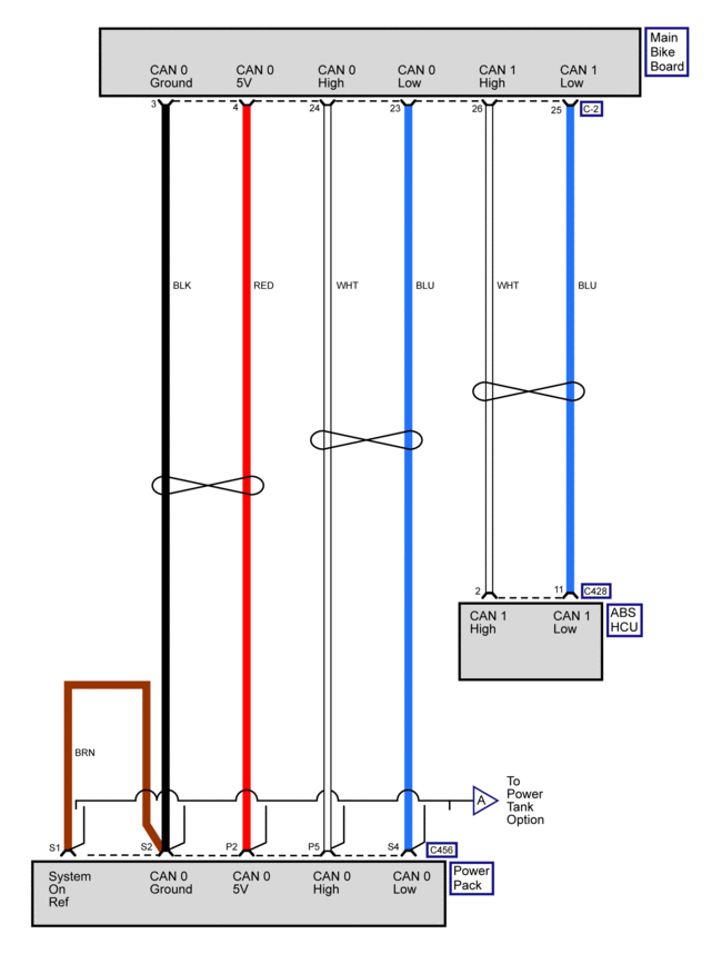
| 3 | BLK | CAN 0 Ground |
| 4 | RED | CAN 0 5 Volts |
| 5 | BLK | CAN 1 Ground |
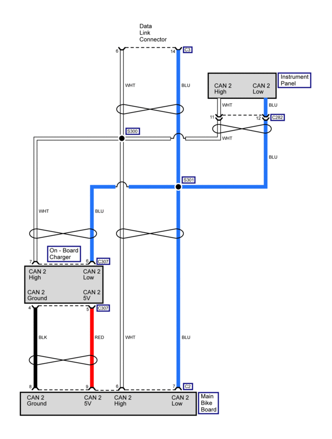
| 6 | WHT | CAN 2 High |
| 7 | BLU | CAN 2 Low |
| 8 | BLK | CAN 2 Ground |
| 9 | RED | CAN 2 5 Volts |
| 10-12 | — | Not Used |
| 13 | PNK | HVIL Return |
| 14 | PNK | HVIL Source |
| 15 | BLU/BLK | Start Switch Input |
| 16 | — | Not Used |
| 17 | BLK | Ambient Temperature |
| 18 | GRY/RED | On Board Charger Attached |
| 19 | ORN/BLK | On Board Charger Reference |
| 20 | WHT/BLK | On Board Charger Enable |
| 21 | BLU/GRY | CAN Low Motor Controller |
| 22 | WHT/GRY | CAN High Motor Controller |
| 23 | BLU | CAN 0 Low |
| 24 | WHT | CAN 0 High |
| 25 | BLU | CAN 1 Low |
| 26 | WHT | CAN 1 High |
| 27 | BLK/GRY | ABS Off |
| 28 | BLK/GRN | ABS Indicator Input |
| 29 | RED/BLK | U-ART Tx |
| 30 | GRY/BLK | U-ART Rx |
| 31 | ORN/BLK | Diagnostic Ground |
| 31 | BLK | Diagnostic Ground |
| 32-33 | — | Not Used |
| 34 | BLU/BRN | Motor Controller Throttle 5V |
| 35 | RED | Ext Switch 5V |
| 36 | GRY/BLU | Chademo Charger Attached |
| 37 | BLU/RED | Motor Controller Throttle 5V |
| 38 | WHT/BLK | Ext Charger Enable 0 |
| 39 | — | Not Used |
| 40 | WHT/BRN | Ext Charger Enable 1 |
| Under the Seat Behind the Power Pack |
|
COM1978
Loading image...

|
Version 1
|
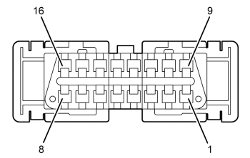
C3 Data Link Connector |
||
|
18502
|
||
|
Connector Part Information |
|
|
|
Pin |
Wire Color |
Function |
| 1-3 | — | Not Used |
| 4 | BLK/BLU | 12 Volt Ground |
| 5 | ORN/BLK | Diagnostic Ground |
| 6 | WHT | CAN 1 High |
| 7 | — | Not Used |
| 8 | RED/BLK | U-ART Tx |
| 9 | GRY/BLK | U-ART Rx |
| 10 | — | Not Used |
| 11 | BLK | CAN 1 Ground |
| 12-13 | — | Not Used |
| 14 | BLU | CAN 1 Low |
| 15-16 | — | Not Used |
| Under the Seat, Behind the Power Pack |
|
COM1978
Loading image...

|
Version 1
|
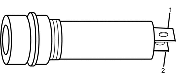
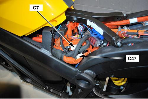
C7 DC/DC Converter Inline Fuse |
||
|
con0770
|
||
|
Connector Part Information |
|
|
|
Pin |
Wire Color |
Function |
| 1 | ORN | Voltage from Power Pack |
| 2 | ORN/BLU | Voltage to DC/DC Converter |
| Under the Fuse Center, Inside harness (inside orange wire loom) |
|
COM1979
Loading image...

|
Version 1
|
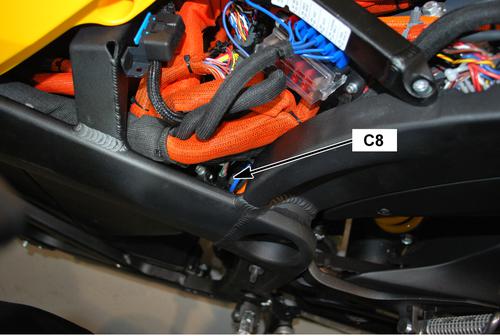
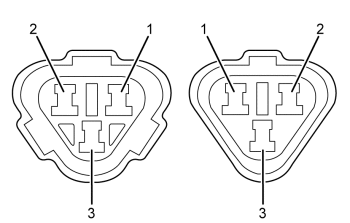
C8 DC/DC Converter |
||
|
18513
|
||
|
Connector Part Information |
|
|
|
Pin |
Wire Color |
Function |
| 1 | BLK | Accessory 0 Volts |
| 2 | BLU | Accessory 12 Volts |
| 3 | ORN/BLK | Negative Input Voltage |
| 4 | ORN/BLU | Positive Input Voltage |
| 5 | ORN/RED | Converter Control |
| Above the Motor, Behind the Main Bike Board |
|
COM1980
Loading image...

|
Version 1
|
18512
Loading image...

|
|||||||
| Connector Part Information |
|
Connector Part Information |
|
||||
| Pin | Wire Color | Function | Pin | Wire Color | Function | ||
| 1 | BLU | 5 Volts | 1 | RED | 5 Volts | ||
| 2 | BLK | Battery Negative | 2 | ORN/BLK | Battery Negative | ||
| 3 | PNK | Kickstand Switch IN Signal | 3 | YEL/BLK | Kickstand Switch IN Signal | ||
| Under the Seat Behind the Power Pack |
|
COM1996
Loading image...

|
Version 1
|
19328
Loading image...

|
|||||
| Connector Part Information |
|
Connector Part Information |
|
||
| Pin | Wire Color | Function | Pin | Wire Color | Function |
| A | WHT | Sine Digital Input | A | BLU | Sine Digital Input |
| B | BLU | Cosine Input | B | WHT | Cosine Input |
| C | BLK | Encoder Power Supply (–) | C | BLK | Encoder Power Supply (–) |
| D | — | Not Used | D | — | Not Used |
| E | PNK | Encoder Power Supply (+) | E | RED | Encoder Power Supply (+) |
| F | GRN | Shield | F | — | Shield |
| G | GRN | Motor Controller Ground | G | ORN/BLK | Motor Controller Ground |
| H | YEL | Temperature Sensor Input | H | WHT | Temperature Sensor Input |
| Under the Seat, Next to the Main Bike Board |
|
COM1984
Loading image...

|
Version 1
|
C26 Accessory Power Port |
||
|
CON0759
|
||
|
Connector Part Information |
|
|
|
Pin |
Wire Color |
Function |
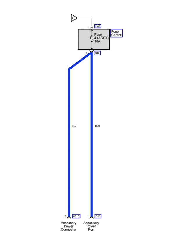
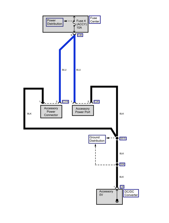
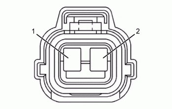
| 1 | BLU | Fuse 4 Voltage |
| 2 | BLK | Ground, Accessory 0 V |
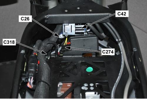
| Front of the Frame, Above the Power Pack |
|
COM1971
Loading image...

|
Version 1
|
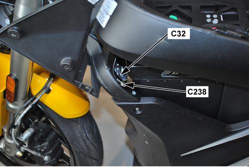
C32 Horn |
||
|
con0758
|
||
|
Connector Part Information |
|
|
|
Pin |
Wire Color |
Function |
|
1 |
BLK/YEL |
Horn Ground Control |
|
C32 Horn |
||
|
con0758
|
||
|
Connector Part Information |
|
|
|
Pin |
Wire Color |
Function |
|
2 |
BLU/BLK |
Horn Supply Voltage |
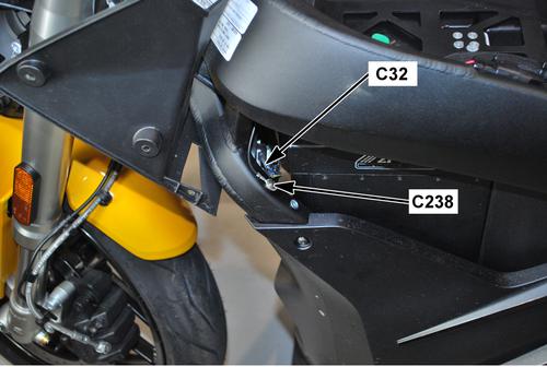
| Front Left Corner of the Power Pack |
|
COM1982
Loading image...

|
Version 1
|
19226
Loading image...

|
|||||
| Connector Part Information |
|
Connector Part Information |
|
||
| Pin | Wire Color | Function | Pin | Wire Color | Function |
| 1 | WHT | Left Front Turn Signal Voltage | 1 | RED/GRN | Left Front Turn Signal Voltage |
|
19226
Loading image...

|
|||||
| Connector Part Information |
|
Connector Part Information |
|
||
| Pin | Wire Color | Function | Pin | Wire Color | Function |
| 2 | BLK | Left Front Turn Signal Ground | 2 | BLK | Left Front Turn Signal Ground |
| Behind the Headlamp Assembly |
|
COM1983
Loading image...

|
Version 1
|
19226
Loading image...

|
|||||
| Connector Part Information |
|
Connector Part Information |
|
||
| Pin | Wire Color | Function | Pin | Wire Color | Function |
| 1 | RED | Right Front Turn Signal Voltage | 1 | WHT/GRY | Right Front Turn Signal Voltage |
|
19226
Loading image...

|
|||||
| Connector Part Information |
|
Connector Part Information |
|
||
| Pin | Wire Color | Function | Pin | Wire Color | Function |
| 2 | BLK | Right Front Turn Signal Ground | 2 | BLK | Right Front Turn Signal Ground |
| Behind the Headlamp Assembly |
|
COM1983
Loading image...

|
Version 1
|
C35
Loading image...

|
|||||
| Connector Part Information |
|
Connector Part Information |
|
||
| Pin | Wire Color | Function | Pin | Wire Color | Function |
| 1 | — | Not Used | 1 | — | Not Used |
| 2 | BRN | High Beam Input (Flash to Pass) | 2 | RED/GRN | High Beam Input (Flash to Pass) |
| 3 | RED/YEL | Headlamp Low Beam Voltage | 3 | BLK | Headlamp Low Beam Voltage |
| 4 | RED/BLK | Headlamp High Beam Voltage | 4 | WHT | Headlamp High Beam Voltage |
| 5 | BLU/YEL | Headlamp Switch Voltage | 5 | BRN | Headlamp Switch Voltage |
| 6 | BLK/YEL | Horn Voltage | 6 | BLU | Horn Voltage |
| 7 | BLK/WHT | Horn Switch Ground | 7 | GRY | Horn Switch Ground |
| 8 | GRY | Right Turn Signal Lamp Voltage | 8 | RED/BLK | Right Turn Signal Lamp Voltage |
| 9 | GRY/GRN | Turn Signal | 9 | BLK/BLU | Turn Signal |
| 10 | GRN | Left Turn Signal Lamp Voltage | 10 | LT BLU | Left Turn Signal Lamp Voltage |
| Behind the Headlight Assembly |
|
COM1983
Loading image...

|
Version 1
|
19227
Loading image...

|
|||||
| Connector Part Information |
|
Connector Part Information |
|
||
| Pin | Wire Color | Function | Pin | Wire Color | Function |
| 1 | BLU/BLK | Foot Brake Switch Supply Voltage | 1 | BLK | Foot Brake Switch Supply Voltage |
| 2 | WHT/RED | Foot Brake Switch Signal | 2 | BLK | Foot Brake Switch Signal |
| Behind the Power Pack, Above the Motor |
|
COM1994
Loading image...

|
Version 1
|
19226
Loading image...

|
|||||
| Connector Part Information |
|
Connector Part Information |
|
||
| Pin | Wire Color | Function | Pin | Wire Color | Function |
| 1 | RED | Left Rear Turn Signal Voltage | 1 | WHT/GRN | Left Rear Turn Signal Voltage |
|
19226
Loading image...

|
|||||
| Connector Part Information |
|
Connector Part Information |
|
||
| Pin | Wire Color | Function | Pin | Wire Color | Function |
| 2 | BLK | Left Rear Turn Signal Ground | 2 | BLK | Left Rear Turn Signal Ground |
| Above the Rear Tire (Seat Removed for Clarity) |
|
COM1985
Loading image...

|
Version 1
|
19226
Loading image...

|
|||||
| Connector Part Information |
|
Connector Part Information |
|
||
| Pin | Wire Color | Function | Pin | Wire Color | Function |
| 1 | RED/BLU | Right Rear Turn Signal Voltage | 1 | RED/GRY | Right Rear Turn Signal Voltage |
|
19226
Loading image...

|
|||||
| Connector Part Information |
|
Connector Part Information |
|
||
| Pin | Wire Color | Function | Pin | Wire Color | Function |
| 2 | BLK | Right Rear Turn Signal Ground | 2 | BLK | Right Rear Turn Signal Ground |
| Above the Rear Tire (Seat Removed for Clarity) |
|
COM1853
Loading image...

|
Version 1
|
C42 Turn Signal Flasher |
|||
|
19225
Loading image...

|
|||
|
Connector Part Information |
|
||
|
Pin |
Wire Color |
Function |
|
| 1 | BLU/BLK | Turn Signal Flasher Voltage | |
| 2 | GRY/GRN | Turn Signal Lamp Control | |
| 3 | BLK | Ground | |
| Front of the Frame, Above the Power Pack |
|
COM1971
Loading image...

|
Version 1
|
C45 Hand Brake Switch |
|||
|
con0758
Loading image...

|
|||
|
Connector Part Information |
|
||
| Pin | Wire Color | Function | |
| 1 | BLU/BLK |
Hand Brake Switch Supply Voltage |
|
|
C45 Hand Brake Switch |
|||
|
con0758
Loading image...

|
|||
|
Connector Part Information |
|
||
| Pin | Wire Color | Function | |
| 2 | WHT/RED |
Hand Brake Switch Signal |
|
| Right Side of the Handlebar, Under the Master Cylinder |
|
com1585
Loading image...

|
Version 1
|
C46 Fuse Center (Bottom View) |
||
|
con0873
|
||
|
Connector Part Information |
|
|
|
Pin |
Wire Color |
Function |
|
1 |
BLU |
Fuse 6 Supply Voltage |
|
2 |
BLU |
Fuse 5 Supply Voltage |
|
3 |
BLU |
Fuse 4 Supply Voltage |
|
4 |
BLU |
Fuse 3 Supply Voltage |
|
5 |
BLU |
Fuse 2 Supply Voltage |
|
6 |
BLU |
Fuse 1 Supply Voltage |
|
7 |
BRN |
Voltage to Splice S28 |
|
8 |
BLU/BLK |
Voltage to Splice S27 |
|
9 |
BLU |
Accessory Power Port |
|
9 |
BLU |
Accessory Power Connector |
|
10 |
BLU/YEL |
Voltage to Splice S25 Headlight Switch |
|
11 |
BLU/GRN |
ABS HCU |
|
12 |
BLU/VIO |
Main Bike Board (MBB) |
| Under the Seat Behind the Power Pack |
|
COM1978
Loading image...

|
Version 1
|
C47 Main Bike Board Inline Fuse |
|||
|
con0770
Loading image...

|
|||
|
Connector Part Information |
|
||
|
Pin |
Wire Color |
Function |
|
| 1 | ORN | Voltage from Power Pack | |
| 2 | ORN/BLU | Voltage to Main Bike Board | |
| Under the Fuse Center, Inside the Harness (inside orange wire loom) |
|
COM1979
Loading image...

|
Version 1
|
C48 Running Light
|
||
|
18077
|
||
|
Connector Part Information
|
|
|
|
Pin
|
Wire Color
|
Function
|
|
1
|
BLK
|
Running Lamp Ground
|
|
2
|
BLU/RED
|
Running Lamp Supply Voltage
|
| Behind the Headlight |
|
COM1864
Loading image...

|
Version 1
|
C45 Hand Brake Switch |
|||
|
con0758
Loading image...

|
|||
|
Connector Part Information |
|
||
| Pin | Wire Color | Function | |
| 1 | BLU/BLK |
Hand Brake Switch Supply Voltage |
|
|
C45 Hand Brake Switch |
|||
|
con0758
Loading image...

|
|||
|
Connector Part Information |
|
||
| Pin | Wire Color | Function | |
| 2 | WHT/RED |
Hand Brake Switch Signal |
|
| Right Side of the Handlebar, Under the Master Cylinder |
|
com1585
Loading image...

|
Version 1
|
C46 Fuse Center (Bottom View) |
||
|
con0873
|
||
|
Connector Part Information |
|
|
|
Pin |
Wire Color |
Function |
|
1 |
BLU |
Fuse 6 Supply Voltage |
|
2 |
BLU |
Fuse 5 Supply Voltage |
|
3 |
BLU |
Fuse 4 Supply Voltage |
|
4 |
BLU |
Fuse 3 Supply Voltage |
|
5 |
BLU |
Fuse 2 Supply Voltage |
|
6 |
BLU |
Fuse 1 Supply Voltage |
|
7 |
BRN |
Voltage to Splice S28 |
|
8 |
BLU/BLK |
Voltage to Splice S27 |
|
9 |
BLU |
Accessory Power Port |
|
9 |
BLU |
Accessory Power Connector |
|
10 |
BLU/YEL |
Voltage to Splice S25 Headlight Switch |
|
11 |
BLU/GRN |
ABS HCU |
|
12 |
BLU/VIO |
Main Bike Board (MBB) |
| Under the Seat Behind the Power Pack |
|
COM1978
Loading image...

|
Version 1
|
C47 Main Bike Board Inline Fuse |
|||
|
con0770
Loading image...

|
|||
|
Connector Part Information |
|
||
|
Pin |
Wire Color |
Function |
|
| 1 | ORN | Voltage from Power Pack | |
| 2 | ORN/BLU | Voltage to Main Bike Board | |
| Under the Fuse Center, Inside the Harness (inside orange wire loom) |
|
COM1979
Loading image...

|
Version 1
|
C48 Running Light
|
||
|
18077
|
||
|
Connector Part Information
|
|
|
|
Pin
|
Wire Color
|
Function
|
|
1
|
BLK
|
Running Lamp Ground
|
|
2
|
BLU/RED
|
Running Lamp Supply Voltage
|
| Behind the Headlight |
|
COM1864
Loading image...

|
Version 1
|
C50 Quick Charge Connector |
||
|
con0761
|
||
|
Connector Part Information |
|
|
|
Pin |
Wire Color |
Function |
|
1 |
BLK |
Fused Battery Positive (+) |
|
2 |
BLK |
Battery Negative (-) |
|
P1-P2 |
— |
Not Used |
|
S1 |
WHT/BRN |
Charger Enable 1 |
|
S2 |
WHT/BLK |
Charger Enable 0 |
| Behind the Power Pack, Above the Motor |
|
COM1849
Loading image...

|
Version 1
|
con0050
|
||
|
Connector Part Information |
|
|
|
Pin |
Wire Color |
Function |
|
— |
ORN/BLK |
Motor Controller Ground |
| Under the Seat, Above the Rear Tire |
|
COM1986
Loading image...

|
|
COM1852
Loading image...

|
Version 1
|
C90 Brushless Motor Controller |
||
|
19332
|
||
|
Connector Part Information |
|
|
|
Pin |
Wire Color |
Function |
| 1 | ORN/RED | Voltage From Key Switch |
| 2 | BLU | CAN Termination |
| 3-5 | — | Not Used |
| 6 | ORN/RED | Voltage From Key Switch |
| 7-14 | — | Not Used |
| 15 | BLK | Encoder Power Supply (–) |
| 16 | WHT/GRY | CAN High |
| 17 | — | Not Used |
| 18 | ORN/GRY | Digital Input 1 |
| 19-20 | — | Not Used |
| 21 | BLU | Digital Input 8 |
| 22 | BRN | Throttle Sensor Signal 1 |
| 23 | BRN/RED | Throttle Sensor Signal 2 |
| 24 | BLU | CAN Low |
| 25 | — | Not Used |
| 26 | RED | Encoder Power Supply (+) |
| 27 | BLU/GRY | CAN Low |
| 28 | YEL/RED | CAN Power Supply (+) |
| 29 | — | Not Used |
| 30 | GRY/ORN | Digital Input 2 (idle switch) |
| 31-32 | — | Not Used |
| 33 | WHT | Temperature Sensor Input |
| 34 | — | Not Used |
| 35 | WHT | COSINE Input |
| Under the Seat, Above the Rear Tire |
|
COM1986
Loading image...

|
|
COM1852
Loading image...

|
Version 1
|
con0756
Loading image...

|
|||||||
| Connector Part Information |
|
Connector Part Information |
|
||||
| Pin | Wire Color | Function | Pin | Wire Color | Function | ||
| 1 | BRN | License Plate Voltage | 1 | PNK | License Plate Voltage | ||
|
con0756
Loading image...

|
|||||||
| Connector Part Information |
|
Connector Part Information |
|
||||
| Pin | Wire Color | Function | Pin | Wire Color | Function | ||
| 2 | BLK | Ground | 2 | BLK | Ground | ||
| Above the Rear Tire (Seat Removed for Clarity) |
|
COM1985
Loading image...

|
Version 1
|
C95 Brushless Motor Controller |
||
|
con0872
|
||
|
Connector Part Information |
|
|
|
Pin |
Wire Color |
Function |
| — | BLK (Orange Sleeve Over Cable) | Positive (+) Voltage |
| — | BLK (Orange Sleeve Over Cable) | Positive (+) Voltage |
| Under the Seat, Above the Rear Tire |
|
Size 4 COM1986
Loading image...

|
|
Size 6 COM1852
Loading image...

|
Version 1
|
C97 Brushless Motor Controller |
||
|
con0051
|
||
|
Connector Part Information |
|
|
|
Pin |
Wire Color |
Function |
| — | BLK (Orange Sleeve Over Cable) | Fused Negative (-) |
| — | BLK (Orange Sleeve Over Cable) | Fused Negative (-) |
| Under the Seat, Above the Rear Tire |
|
COM1986
Loading image...

|
|
COM1852
Loading image...

|
Version 1
|
C106 Headlight |
||
|
19225
|
||
|
Connector Part Information |
|
|
|
Pin |
Wire Color |
Function |
|
1 |
RED/BLK |
High Beam Light Supply Voltage |
|
2 |
RED/YEL |
Low Beam Light Supply Voltage |
|
3 |
BLK |
Headlight Ground |
| Behind the Headlight |
|
COM1864
Loading image...

|
Version 1
|
con0760
Loading image...

|
|||||||
| Connector Part Information |
|
Connector Part Information |
|
||||
| Pin | Wire Color | Function | Pin | Wire Color | Function | ||
| 1 | BLK | Running Light Ground | 1 | BLK | Running Light Ground | ||
| 2 | BLU/RED | Front Running Light Voltage | 2 | BRN | Front Running Light Voltage | ||
| Behind the Front Headlight Assembly |
|
COM1864
Loading image...

|
Version 1
|
C113 Brushless Motor Controller |
||
|
con0051
|
||
|
Connector Part Information |
|
|
|
Pin |
Wire Color |
Function |
| — | BLK (Orange Sleeve Over Cable) | M1 Going to the Motor |
| Under the Seat, Above the Rear Tire |
|
Size 4 COM1986
Loading image...

|
|
Size 6 COM1852
Loading image...

|
Version 1
|
C114 Brushless Motor Controller |
||
|
con0051
|
||
|
Connector Part Information |
|
|
|
Pin |
Wire Color |
Function |
| — | BLK (Orange Sleeve Over Cable) | Going to the Motor |
| Under the Seat, Above the Rear Tire |
|
Size 4 COM1986
Loading image...

|
|
Size 6 COM1852
Loading image...

|
Version 1
|
C115 Brushless Motor Controller |
||
|
con0051
|
||
|
Connector Part Information |
|
|
|
Pin |
Wire Color |
Function |
| — | BLK (Orange Sleeve Over Cable) | Going to the Motor |
| Under the Seat, Above the Rear Tire |
|
COM1986
Loading image...

|
|
COM1852
Loading image...

|
Version 1
|
con0755
Loading image...

|
|||||||
| Connector Part Information |
|
Connector Part Information |
|
||||
| Pin | Wire Color | Function | Pin | Wire Color | Function | ||
| 1 | GRN/YEL | Chassis Isolation | 1 | GRN/YEL | Chassis Isolation | ||
| Under the Seat, Behind the Power Pack |
|
COM1987
Loading image...

|
Version 1
|
con0754
Loading image...

|
|||||||
| Connector Part Information |
|
Connector Part Information |
|
||||
| Pin | Wire Color | Function | Pin | Wire Color | Function | ||
| 1 | WHT/BLK | Charger Enable 0 | 1 | WHT/BLK | Charger Enable 0 | ||
| 2 | WHT/BRN | Charger Enable 1 | 2 | WHT/BRN | Charger Enable 1 | ||
| Under the Seat, Behind the Power Pack |
|
COM1997
Loading image...

|
Version 1
|
con0050
|
||
|
Connector Part Information |
|
|
|
Pin |
Wire Color |
Function |
| — | BLK | Equipment Ground |
| Left Frame Front of the Frame, Next to the Horn |
|
com1982
Loading image...

|
Version 1
|
C239 Equipment Ground |
||
|
con0050
|
||
|
Connector Part Information |
|
|
|
Pin |
Wire Color |
Function |
| — | BLK | Equipment Ground |
| Behind the Headlight, On the Left Side of the Fork |
|
COM1865
Loading image...

|
Version 1
|
18510
Loading image...

|
|||||||
| Connector Part Information |
|
Connector Part Information |
|
||||
| Pin | Wire Color | Function | Pin | Wire Color | Function | ||
| 1 | — | Not Used | 1 | GRY | Not Used | ||
| 2 | — | Not Used | 2 | BRN | Not Used | ||
| 3 | YEL/GRY | Key Switch Ground | 3 | RED | Key Switch Ground | ||
| 4 | YEL/GRN | Key Switch Signal | 4 | RED/BLK | Key Switch Signal | ||
| Front of the Frame, Above the Power Pack |
|
COM1971
Loading image...

|
Version 1
|
con0753
Loading image...

|
|||||||
| Connector Part Information |
|
Connector Part Information |
|
||||
| Pin | Wire Color | Function | Pin | Wire Color | Function | ||
| 1 | BLU/BLK | Start Switch Signal | 1 | BLK | Start Switch Signal | ||
| 2 | RED | Switch 5 Volts | 2 | BLU/WHT | Switch 5 Volts | ||
| 3 | RED | Motor Stop Switch Output 5 Volts | 3 | RED/WHT | Motor Stop Switch Output 5 Volts | ||
| 4 | RED/BLK | Motor Stop Switch Input | 4 | RED/WHT | Motor Stop Switch Input | ||
| Behind the Front Headlight Assembly |
|
COM1983
Loading image...

|
Version 1
|
CON0752
Loading image...

|
|||||||
| Connector Part Information |
|
Connector Part Information |
|
||||
| Pin | Wire Color | Function | Pin | Wire Color | Function | ||
| 1 | YEL/BLK | Warning Light Control (red) | 1 | YEL/BLK | Warning Light Control (red) | ||
| 2 | YEL | Temperature Light Control (amber) | 2 | YEL | Temperature Light Control (amber) | ||
| 3 | RED/WHT | Armed Light Control (green) | 3 | GRN | Armed Light Control (green) | ||
| 4 | VIO | Charge LED Light Control (green) | 4 | WHT/BLK | Charge LED Light Control (green) | ||
| 5 | WHT/BLU | Check Engine Light Control | 5 | BLU | Check Engine Light Control | ||
| 6 | RED/BLK | High Beam Indicator Control (blue) | 6 | BRN/BLK | High Beam Indicator Control (blue) | ||
| 7 | GRN | Left Turn Indicator Control (green) | 7 | GRN | Left Turn Indicator Control (green) | ||
| 8 | GRY | Right Turn Indicator Control (green) | 8 | GRY | Right Turn Indicator Control (green) | ||
| 9 | BLK | Ground 12 Volt | 9 | BLK | Ground 12 Volt | ||
| 10 | RED | State of Charge Control (5 Volt) | 10 | PNK | State of Charge Control (5 Volt) | ||
| 11 | WHT | CAN 2 High | 11 | WHT | CAN 2 High | ||
| 12 | BLU | CAN 2 Low | 12 | BLU | CAN 2 Low | ||
| 13 | ORN/BLK | CAN 2 5 Volts | 13 | ORN | CAN 2 5 Volts | ||
| 14 | BLU/WHT | ABS | 14 | GRY | ABS | ||
| 15 | ORN | Charge LED Light Control (red) | 15 | ORN | Charge LED Light Control (red) | ||
| 16 | BRN | 12 Volt Feed | 16 | BRN | 12 Volt Feed | ||
| 17-20 | — | Not Used | 17-20 | — | Not Used | ||
| Left Upper Side of the Frame, Above the Power Pack |
|
COM1988
Loading image...

|
Version 1
|
con0751
Loading image...

|
|||||||
| Connector Part Information |
|
Connector Part Information |
|
||||
| Pin | Wire Color | Function | Pin | Wire Color | Function | ||
| 1 | BRN | Running Light Supply Voltage | 1 | ORN/BLK | Running Light Supply Voltage | ||
| 2 | WHT/RED | Brake Light Supply Voltage | 2 | YEL/RED | Brake Light Supply Voltage | ||
| 3 | BLK | Tail Light Ground | 3 | BLK | Tail Light Ground | ||
| Above the Rear Tire (Seat Removed For Clarity) |
|
COM1985
Loading image...

|
Version 1
|
con0762
Loading image...

|
|||||||
| Connector Part Information |
|
Connector Part Information |
|
||||
| Pin | Wire Color | Function | Pin | Wire Color | Function | ||
| 1 | BLK | Fused Battery Positive Voltage (+) | 1 | BLK | Fused Battery Positive Voltage (+) | ||
| 2 | BLK | Battery Negative (-) | 2 | BLK | Battery Negative (-) | ||
| In Front of the Motor |
|
COM1989
Loading image...

|
Version 1
|
C307 Charger |
||
|
con0748
|
||
|
Connector Part Information |
|
|
|
Pin |
Wire Color |
Function |
| 1 | — | Not Used |
| 2 | GRY/BLU | Chademo Charger Attached |
| 3 | — | Not Used |
| 4 | BLK | CAN Ground |
| 5 | RED | CAN 5V |
| 6 | BLU | CAN 2 Low |
| 7 | WHT | CAN 2 High |
| 8-10 | — | Not Used |
| 11 | GRY/RED | Charger Attached Signal |
| 12 | WHT/BLK | Charger Enable |
| 13 | ORN/BLK | Charger Ground |
| 14-18 | — | Not Used |
| Above the Bottom Skid Plate, In Front of the Motor |
|
com1598
Loading image...

|
Version 1
|
C318 12 Volt Accessory Connector |
||
|
con0749
|
||
|
Connector Part Information |
|
|
|
Pin |
Wire Color |
Function |
| 1 | BLK | Ground, Accessory 0 V |
| 2 | BLU | Fuse 4 Voltage |
| Front of the Frame, Above the Power Pack |
|
COM1971
Loading image...

|
Version 1
|
C366 Power Tank Signal |
||
|
con0766
|
||
|
Connector Part Information |
|
|
|
Pin |
Wire Color |
Function |
| P1 | — | Not Used |
| P2 | RED | CAN 5 Volts |
| P3 | — | Not Used |
| P4 | YEL/GRY | 12 Volt Output |
| P5 | WHT | CAN High |
| P6 | — | Not Used |
| P7 | GRY/BRN | Node ID 1 |
| P8 | GRY/BRN | Ground |
| S1 | BRN | System ON Reference |
| S2 | BLK | CAN Ground |
| S3 | BRN/WHT | System ON |
| S4 | BLU | CAN Low |
| S5 | PNK | HVIL Output |
| S6 | GRN/YEL | Chassis Ground |
| S7 | PNK | HVIL Return |
| S8 | BLK/WHT | Throttle Enable |
| Under the Tank Assembly, On Top of the Power Tank |
|
com1454
Loading image...

|
Version 1
|
C367 Power Tank Power Pack |
||
|
con0766
|
||
|
Connector Part Information |
|
|
|
Pin |
Wire Color |
Function |
| - | BLK | Battery Positive (+) |
| - | BLK | Battery Negative (-) |
| Under the Seat, Above the Rear Tire |
|
com1454
Loading image...

|
Version 1
|
C368 Power Tank Battery Positive (+) |
||
|
con0907
|
||
|
Connector Part Information |
|
|
|
Pin |
Wire Color |
Function |
| — | BLK | Switched Battery Positive (+) |
| Under the Seat, Above the Rear Tire |
|
com1990
Loading image...

|
Version 1
|
C307 Charger |
||
|
con0748
|
||
|
Connector Part Information |
|
|
|
Pin |
Wire Color |
Function |
| 1 | — | Not Used |
| 2 | GRY/BLU | Chademo Charger Attached |
| 3 | — | Not Used |
| 4 | BLK | CAN Ground |
| 5 | RED | CAN 5V |
| 6 | BLU | CAN 2 Low |
| 7 | WHT | CAN 2 High |
| 8-10 | — | Not Used |
| 11 | GRY/RED | Charger Attached Signal |
| 12 | WHT/BLK | Charger Enable |
| 13 | ORN/BLK | Charger Ground |
| 14-18 | — | Not Used |
| Above the Bottom Skid Plate, In Front of the Motor |
|
com1598
Loading image...

|
Version 1
|
C318 12 Volt Accessory Connector |
||
|
con0749
|
||
|
Connector Part Information |
|
|
|
Pin |
Wire Color |
Function |
| 1 | BLK | Ground, Accessory 0 V |
| 2 | BLU | Fuse 4 Voltage |
| Front of the Frame, Above the Power Pack |
|
COM1971
Loading image...

|
Version 1
|
C366 Power Tank Signal |
||
|
con0766
|
||
|
Connector Part Information |
|
|
|
Pin |
Wire Color |
Function |
| P1 | — | Not Used |
| P2 | RED | CAN 5 Volts |
| P3 | — | Not Used |
| P4 | YEL/GRY | 12 Volt Output |
| P5 | WHT | CAN High |
| P6 | — | Not Used |
| P7 | GRY/BRN | Node ID 1 |
| P8 | GRY/BRN | Ground |
| S1 | BRN | System ON Reference |
| S2 | BLK | CAN Ground |
| S3 | BRN/WHT | System ON |
| S4 | BLU | CAN Low |
| S5 | PNK | HVIL Output |
| S6 | GRN/YEL | Chassis Ground |
| S7 | PNK | HVIL Return |
| S8 | BLK/WHT | Throttle Enable |
| Under the Tank Assembly, On Top of the Power Tank |
|
com1454
Loading image...

|
Version 1
|
C367 Power Tank Power Pack |
||
|
con0766
|
||
|
Connector Part Information |
|
|
|
Pin |
Wire Color |
Function |
| - | BLK | Battery Positive (+) |
| - | BLK | Battery Negative (-) |
| Under the Seat, Above the Rear Tire |
|
com1454
Loading image...

|
Version 1
|
C368 Power Tank Battery Positive (+) |
||
|
con0907
|
||
|
Connector Part Information |
|
|
|
Pin |
Wire Color |
Function |
| — | BLK | Switched Battery Positive (+) |
| Under the Seat, Above the Rear Tire |
|
com1990
Loading image...

|
Version 1
|
C369 Power Tank Battery Negative (-) |
||
|
con0907
|
||
|
Connector Part Information |
|
|
|
Pin |
Wire Color |
Function |
| — | BLK | Battery Negative (-) |
| Under the Seat, Above the Rear Tire |
|
com1990
Loading image...

|
Version 1
|
C428 ABS Hydraulic Control Unit |
||
|
con0869
|
||
|
Connector Part Information |
|
|
|
Pin |
Wire Color |
Function |
| 1 | BLK | Ground |
| 2 | WHT | CAN |
| 3 | BLK/WHT | Front Wheel Speed Sensor (WSS) |
| 4 | WHT/GRN | WAU Input |
| 5-8 | - | Not Used |
| 9 | BLU/GRN | Fuse 2 Voltage |
| 10 | BLK | Motor Ground |
| 11 | BLU | CAN |
| 12 | BLK/RED | Front Wheel Speed Sensor (WSP) |
| 13 | BLK/RED |
Rear Wheel Speed Sensor (WSP) |
| 14 | BLK/WHT | Rear Wheel Speed Sensor (WSS) |
| 15 | BLK/GRY | OFF Output |
| 16 | - | Not Used |
| 17 | BLK/GRN | Indicator Control Output |
| 18 | BLU/ORG | In-Line Fuse (ABS Pump) |
| Under the Front of the Frame, Above the Front Corner of the Battery |
|
com1995
Loading image...

|
Version 1
|
C429 Front Wheel Speed Sensor |
||
|
con0462
|
||
|
Connector Part Information |
|
|
|
Pin |
Wire Color |
Function |
| 1 | BLK/RED | WSP |
| 2 | BLK/WHT | WSS |
| Behind the Headlight |
|
COM1983
Loading image...

|
Version 1
|
C430 Rear Wheel Speed Sensor |
||
|
con0462
|
||
|
Connector Part Information |
|
|
|
Pin |
Wire Color |
Function |
| 1 | BLK/RED | WSP |
| 2 | BLK/WHT | WSS |
| Under the Seat Bracket, Behind the Power Pack |
|
COM1987
Loading image...

|
Version 1
|
C456 Power Pack Signal |
||
|
con1008
|
||
|
Connector Part Information |
|
|
|
Pin |
Wire Color |
Function |
| P1 |
ORN ORN ORN ORN |
Low Power B+ |
| P2 |
RED RED |
CAN 5 Volts |
| P3 |
- |
Not Used |
| P4 |
YEL/GRY YEL/GRY |
12 Volt Output |
| P5 |
WHT WHT |
CAN High |
| P6 | GRY/BRN | Node ID 0 |
| P7 | GRY/BRN | Node ID 1 |
| P8 |
GRY/BRN GRY/BRN |
Ground |
| S1 |
BRN BRN |
System ON Reference |
| S2 |
BLK BLK BRN |
CAN Ground |
| S3 |
BRN/WHT BRN/WHT |
System ON |
| S4 |
BLU BLU |
CAN Low |
| S5 | PNK | HVIL Output |
| S6 |
GRN/YEL GRN/YEL |
Chassis Ground |
| S7 | PNK | HVIL Input |
| S8 |
BLK/WHT BLK/WHT |
Throttle Enable MBB |
| Top of the Power Pack, Under the Tank |
|
COM1993
Loading image...

|
Version 1
|
con0908
Loading image...

|
|||||||
| Connector Part Information |
|
Connector Part Information |
|
||||
| Pin | Wire Color | Function | Pin | Wire Color | Function | ||
| 1 | BLU/RED | Sensor 2 Voltage 5V | 1 | BLK | Sensor 2 Voltage 5V | ||
| 2 | BRN/RED | Sensor 2 Signal | 2 | BLU | Sensor 2 Signal | ||
| 3 | ORN/BLK | Ground | 3 | RED | Ground | ||
| 4 | - | Not Used | 4 | BRN | Not Used | ||
| 5 | ORN/BLK | Ground | 5 | BRN | Ground | ||
| 6 | BRN | Sensor 1 Signal | 6 | RED | Sensor 1 Signal | ||
| 7 | BLU/BRN | Sensor 1 Voltage 5V | 7 | YEL | Sensor 1 Voltage 5V | ||
| 8 | GRY/ORN | Idle Switch | 8 | GRN | Idle Switch | ||
| Behind the Headlamp Assembly |
|
COM1983
Loading image...

|
Version 1
|
C469 Power Pack |
||
|
con1007
|
||
|
Connector Part Information |
|
|
|
Pin |
Wire Color |
Function |
| 1 | BLK | Battery Positive (+) |
| 2 | BLK | Battery Positive (-) |
| Top of the Power Pack, Under the Tank |
|
COM1993
Loading image...

|
Version 1
|
con0768
Loading image...

|
|||||||
| Connector Part Information |
|
Connector Part Information |
|
||||
| Pin | Wire Color | Function | Pin | Wire Color | Function | ||
| 1 | BRN | System ON Reference | 1 | BRN | System ON Reference | ||
| 2 | BRN/WHT | System ON | 2 | BRN/WHT | System ON | ||
| 3 | BLU | CAN Low | 3 | BLU | CAN Low | ||
| 4 | RED | CAN 5 Volt | 4 | RED | CAN 5 Volt | ||
| 5 | PNK | HVIL Source | 5 | PNK | HVIL Source | ||
| 5 | PNK | HVIL Source (loop to pin 13)(without power pack) | 5 | PNK | HVIL Source | ||
| 6 | GRY/RED | On Board Charger Attached | 6 | GRY/RED | On Board Charger Attached | ||
| 6 | GRY | On Board Charger Attached (loop to pin 7)(without power pack) | 6 | GRY/RED | On Board Charger Attached | ||
| 7 | GRY/RED | On Board Charger Attached | 7 | GRY/RED | On Board Charger Attached | ||
| 7 | GRY | On Board Charger Attached (loop to pin 6)(without power pack) | 7 | GRY/RED | On Board Charger Attached | ||
| 8 | - | Not Used | 8 | - | Not Used | ||
| 9 | - | Not Used | 9 | ORN | MBB and DC/DC Converter Low Power (-) | ||
| 10 | - | Not Used | 10 | ORN | Fuse DC/DC Converter Low Power (+) | ||
| 11 | WHT | CAN High | 11 | WHT | CAN High | ||
| 12 | BLK | CAN Ground | 12 | BLK | CAN Ground | ||
| 13 | PNK | HVIL Source (loop to pin 5)(without power pack) | 13 | PNK | HVIL Return | ||
| 13 | PNK | HVIL Return | 13 | PNK | HVIL Return | ||
| 14 | BLK/WHT | Throttle Enable | 14 | BLK/WHT | Throttle Enable | ||
| 15 | GRN/YEL | Chassis Ground | 15 | GRN/YEL | Chassis Ground | ||
| 16 | YEL/GRY | 12 Volt Output | 16 | YEL/GRY | 12 Volt Output | ||
| Under the Seat, Below the Fuse Center |
|
COM1991
Loading image...

|
Version 1
|
D11 Inline Temperature Sensor |
||
|
Image Not Available
|
||
|
Pin |
Wire Color |
Function |
| 1 | BLK | Temperature Sensor 1 Input |
| 2 | BLK | Ground |
| Front of the Frame, Above the Power Pack (sticking out of the harness) |
|
COM1991
Loading image...

|
Version 1
|
D143 ABS Pump Inline Fuse |
||
|
Image Not Available |
||
|
Connector Part Information |
|
|
|
Pin |
Wire Color |
Function |
| 1 | BLU | Voltage From DC/DC Converter |
| 2 | BLU/ORN | Voltage to ABS HCU Converter |
| Under the Seat, Next to the Fuse Center |
|
COM1981
Loading image...

|
Version 1
|
D305 Charger Fuse |
||
|
con0051
|
||
|
Connector Part Information |
|
|
|
Pin |
Wire Color |
Function |
| 1 | BLK (Orange Sleeve Over Cable) | Positive (+) Input |
|
con0051
|
||
|
Connector Part Information |
|
|
|
Pin |
Wire Color |
Function |
| 2 | BLK (Orange Sleeve Over Cable) | Battery Positive (+) Output |
| Behind the Right Side of the Power Pack, Under the Seat |
|
COM1989
Loading image...

|
Version 1
Left Side of the Frame, Next to the Tank Compartment/Power Tank

|
Joint |
Connector |
Pin |
Color |
Function |
|
Loading image...

|
C35 | 8 | GRY | Right Turn Signal Input |
|
Loading image...

|
C282 | 8 | GRY | Right Turn Signal Output |
|
Loading image...

|
C40 | 1 | RED/GRY | Right Turn Signal Output |
|
Loading image...

|
C34 | 1 | WHT/GRY | Right Turn Signal Output |
Version 1
Left Side of the Frame, Next to the Tank Compartment/Power Tank

|
Joint |
Connector |
Pin |
Color |
Function |
|
Loading image...

|
C35 | 10 | GRN | Left Turn Signal Input |
|
Loading image...

|
C282 | 7 | GRN | Left Turn Signal Output |
|
Loading image...

|
C39 | 1 | WHT/GRN | Left Turn Signal Output |
|
Loading image...

|
C33 | 1 | RED/GRN | Left Turn Signal Output |
Version 1
Left Side of the Frame, Under the 12 Volt Fuse Center

|
Joint |
Connector |
Pin |
Color |
Function |
|
Loading image...

|
C8 | 2 | BLU | 12 Volt Input |
|
Loading image...

|
C46 | 1 | BLU | 12 Volt Output |
|
Loading image...

|
C46 | 2 | BLU | 12 Volt Output |
|
Loading image...

|
C46 | 3 | BLU | 12 Volt Output |
|
Loading image...

|
C46 | 4 | BLU | 12 Volt Output |
|
Loading image...

|
C46 | 5 | BLU | 12 Volt Output |
|
Loading image...

|
C46 | 6 | BLU | 12 Volt Output |
|
Loading image...

|
C143 | 1 | BLU | 12 Volt Output |
Version 1
Left Side of the Frame, Next to the Tank Compartment/Power Tank

|
Joint |
Connector |
Pin |
Color |
Function |
|
Loading image...

|
C8 | 1 | BLK | 12 Volt Ground Input |
|
Loading image...

|
C40 | 2 | BLK | 12 Volt Ground Output |
|
Loading image...

|
C1 | 29 | BLK | 12 Volt Ground Output |
|
Loading image...

|
C3 | 4 | BLK/BLU | 12 Volt Ground Output |
|
Loading image...

|
C39 | 2 | BLK | 12 Volt Ground Output |
|
Loading image...

|
C303 | 3 | BLK | 12 Volt Ground Output |
|
Loading image...

|
C93 | 2 | BLK | 12 Volt Ground Output |
|
Loading image...

|
S515 | — | BLK | 12 Volt Ground Output to Splice S515 |
Version 1
Left Side of the Frame, Next to the Tank Compartment/Power Tank

|
Joint |
Connector |
Pin |
Color |
Function |
|
Loading image...

|
C46 | 10 | BLU/YEL | 12 Volt Input (fuse 3) |
|
Loading image...

|
C35 | 5 | BLU/YEL | High/Low Beam Headlight |
|
Loading image...

|
C35 | 2 | BRN | Flash to Pass |
Version 1
Left Side of the Frame, Next to the Tank Compartment/Power Tank

|
Joint |
Connector |
Pin |
Color |
Function |
|
Loading image...

|
C46 | 8 | BLU/BLK | 12 Volt Input (fuse 5) |
|
Loading image...

|
C38 | 1 | BLU/BLK | Foot Brake Light Switch |
|
Loading image...

|
C45 | 1 | BLU/BLK | Hand Brake Light Switch |
|
Loading image...

|
C42 | 1 | BLU/BLK | Turn Signal Flasher |
|
Loading image...

|
C32 | 2 | BLU/BLK | Horn |
Version 1
Left Side of the Frame, Next to the Tank Compartment/Power Tank

|
Joint |
Connector |
Pin |
Color |
Function |
|
Loading image...

|
C46 | 7 | BRN | 12 Volt Input (fuse 6) |
|
Loading image...

|
C303 | 1 | BRN | Rear Running Light |
|
Loading image...

|
C107 | 2 | BRN | Front Running Light |
|
Loading image...

|
C93 | 1 | BRN | License Plate Light |
|
Loading image...

|
C282 | 16 | BRN | Instrument Panel |
Version 1
Behind the Headlight

|
Joint |
Connector |
Pin |
Color |
Function |
|
Loading image...

|
C35 | 4 | RED/BLK | Headlight Switch Output |
|
Loading image...

|
C106 | 1 | RED/BLK | Headlight Switch Output |
|
Loading image...

|
C282 | 6 | RED/BLK | I/P High Beam Indicator Control Input |
Version 1
Left Side of the Frame, Next to the Tank Compartment/Power Tank

|
Joint |
Connector |
Pin |
Color |
Function |
|
Loading image...

|
C45 | 2 | WHT/RED | Hand Brake Light Switch Output |
|
Loading image...

|
C303 | 2 | WHT/RED | Brake Light Input |
|
Loading image...

|
C38 | 2 | WHT/RED | Foot Brake Light Switch Output |
|
Loading image...

|
C1 | 28 | WHT/RED | Brake Light Switch Input |
Version 1
Under the Seat, Above the Brushless Motor Controller

|
Joint |
Connector |
Pin |
Color |
Function |
|
Loading image...

|
C89 | 1 | ORN/BLK | Brushless Motor Controller (ground) |
|
Loading image...

|
C2 | 1 | ORN/BLK | Main Bike Board (MBB) |
|
Loading image...

|
C14 | G | ORN/BLK | Motor |
|
Loading image...

|
C459 | 3 | ORN/BLK | Throttle Position 1 |
|
Loading image...

|
C8 | 3 | ORN/BLK | DC/DC Converter |
|
Loading image...

|
C1 | 7 | ORN/BLK | Main Bike Board (MBB) |
|
Loading image...

|
C459 | 5 | ORN/BLK | Throttle Position 2 |
Version 1
Under the Seat, in Front of the Main Bike Board

|
Joint |
Connector |
Pin |
Color |
Function |
|
Loading image...

|
C2 | 6 | WHT | CAN 2 High |
|
Loading image...

|
C282 | 11 | WHT | CAN 2 High |
|
Loading image...

|
C3 | 6 | WHT | CAN 2 High |
|
Loading image...

|
C307 | 7 | WHT | CAN 2 High |
Version 1
Under the Seat, in Front of the Main Bike Board

|
Joint |
Connector |
Pin |
Color |
Function |
|
Loading image...

|
C2 | 7 | BLU | CAN 2 Low |
|
Loading image...

|
C282 | 12 | BLU | CAN 2 Low |
|
Loading image...

|
C3 | 14 | BLU | CAN 2 Low |
|
Loading image...

|
C307 | 6 | BLU | CAN 2 Low |
Version 1
Left Side of the Frame, Next to the Tank Compartment/Power Tank

|
Joint |
Connector |
Pin |
Color |
Function |
|
Loading image...

|
— | — | BLK | 12 Volt Ground Input from Splice S24 |
|
Loading image...

|
C106 | 3 | BLK | 12 Volt Ground Output |
|
Loading image...

|
C107 | 1 | BLK | 12 Volt Ground Output |
|
Loading image...

|
C428 | 1 | BLK | 12 Volt Ground Output |
|
Loading image...

|
C33 | 2 | BLK | 12 Volt Ground Output |
|
Loading image...

|
C42 | 3 | BLK | 12 Volt Ground Output |
|
Loading image...

|
C428 | 10 | BLK | 12 Volt Ground Output |
|
Loading image...

|
C34 | 2 | BLK | 12 Volt Ground Output |
|
Loading image...

|
C318 | 1 | BLK | 12 Volt Ground Output |
|
Loading image...

|
C35 | 7 | BLK/WHT | 12 Volt Ground Output |
|
Loading image...

|
C282 | 9 | BLK | 12 Volt Ground Output |
|
Loading image...

|
C26 | 2 | BLK | 12 Volt Ground Output |
Version 1
Under the Seat, Above the Brushless Motor Controller

|
Joint |
Connector |
Pin |
Color |
Function |
|
Loading image...

|
C89 | 1 | ORN/BLK | Brushless Motor Controller (ground) |
|
Loading image...

|
C2 | 1 | ORN/BLK | Main Bike Board (MBB) |
|
Loading image...

|
C14 | G | ORN/BLK | Motor |
|
Loading image...

|
C459 | 3 | ORN/BLK | Throttle Position 1 |
|
Loading image...

|
C8 | 3 | ORN/BLK | DC/DC Converter |
|
Loading image...

|
C1 | 7 | ORN/BLK | Main Bike Board (MBB) |
|
Loading image...

|
C459 | 5 | ORN/BLK | Throttle Position 2 |
Version 1
Under the Seat, in Front of the Main Bike Board

|
Joint |
Connector |
Pin |
Color |
Function |
|
Loading image...

|
C2 | 6 | WHT | CAN 2 High |
|
Loading image...

|
C282 | 11 | WHT | CAN 2 High |
|
Loading image...

|
C3 | 6 | WHT | CAN 2 High |
|
Loading image...

|
C307 | 7 | WHT | CAN 2 High |
Version 1
Under the Seat, in Front of the Main Bike Board

|
Joint |
Connector |
Pin |
Color |
Function |
|
Loading image...

|
C2 | 7 | BLU | CAN 2 Low |
|
Loading image...

|
C282 | 12 | BLU | CAN 2 Low |
|
Loading image...

|
C3 | 14 | BLU | CAN 2 Low |
|
Loading image...

|
C307 | 6 | BLU | CAN 2 Low |
Version 1
Left Side of the Frame, Next to the Tank Compartment/Power Tank

|
Joint |
Connector |
Pin |
Color |
Function |
|
Loading image...

|
— | — | BLK | 12 Volt Ground Input from Splice S24 |
|
Loading image...

|
C106 | 3 | BLK | 12 Volt Ground Output |
|
Loading image...

|
C107 | 1 | BLK | 12 Volt Ground Output |
|
Loading image...

|
C428 | 1 | BLK | 12 Volt Ground Output |
|
Loading image...

|
C33 | 2 | BLK | 12 Volt Ground Output |
|
Loading image...

|
C42 | 3 | BLK | 12 Volt Ground Output |
|
Loading image...

|
C428 | 10 | BLK | 12 Volt Ground Output |
|
Loading image...

|
C34 | 2 | BLK | 12 Volt Ground Output |
|
Loading image...

|
C318 | 1 | BLK | 12 Volt Ground Output |
|
Loading image...

|
C35 | 7 | BLK/WHT | 12 Volt Ground Output |
|
Loading image...

|
C282 | 9 | BLK | 12 Volt Ground Output |
|
Loading image...

|
C26 | 2 | BLK | 12 Volt Ground Output |
Version 1
|
C1 Main Bike Board |
|||
|
18007
|
|||
|
Connector Part Information |
|
||
|
Pin |
Wire Color |
Function |
|
| 1 | ORN/RED | Motor Controller Enable | |
| 1 | ORN/RED | Motor Controller Enable | |
| 2 | — | Not Used | |
| 3 | WHT/GRN | ABS HCU Voltage | |
| 4 | BLU | Fuse 1 ABS 4 Key, 12 Volt Positive | |
| 5-6 | — | Not Used | |
| 7 | ORN/BLK | Power Pack Ground | |
| 8 | BRN | System ON Reference | |
| 9 | BRN/WHT | System ON Output | |
| 10 | — | Not Used | |
| 11 | YEL/BLK | Kickstand Switch Signal | |
| 12 | ORN/BLK | Kickstand Switch Ground | |
| 13 | WHT/BLU | Check Engine Light Control | |
| 14 | RED | Fuel Gauge 5V Reference | |
| 15 | YEL/GRN | Key ON 12V | |
| 16 | YEL | Temperature Warning Lamp Control | |
| 17 | YEL/BLK | Warning Lamp Control | |
| 18 | ORN/BRN | MBB Low Power | |
| 19 | ORN/GRY | Motor Controller Neutral | |
| 20 | ORN/RED | DC/DC Converter Enable | |
| 21 | — | Not Used | |
| 22 | BLK/WHT | Battery Throttle Enable | |
| 23 | RED | Ext Switch 5V | |
| 24 | RED/BLK | Motor Stop Switch IN | |
| 25-26 | — | Not Used | |
| 27 | RED | Kickstand Switch Signal 5V | |
| 28 | WHT/RED | Brake Switch Input | |
| 29 | BLK | 12 Volt Ground | |
| 30 | BLU/WHT | ABS Indicator Light Control | |
| 31 | ORN | Red Charge Indicator Light Control | |
| 32 | ORN/BLK | Instrument Cluster Light Ground | |
| 33 | VIO | Charge Indicator Control | |
| 34 | RED/WHT | Armed Indicator Light Control | |
| Under the Seat Behind the Power Pack |
|
COM1978
Loading image...

|
Version 1
|
C2 Main Bike Board |
||
|
CON0765
|
||
|
Connector Part Information |
|
|
|
Pin |
Wire Color |
Function |
| 1 | ORN/BLK | Motor Controller Ground |
| 2 | YEL/RED | Motor Controller 24 Volt |
| 3 | BLK | CAN 0 Ground |
| 4 | RED | CAN 0 5 Volts |
| 5 | BLK | CAN 1 Ground |
| 6 | WHT WHT |
CAN 2 High CAN 2 High |
| 7 | BLU BLU |
CAN 2 Low CAN 2 Low |
| 8 | BLK | CAN 2 Ground |
| 9 | RED | CAN 2 5 Volts |
| 10 | RED/ORN | Diagnostic 3, 3 Volts |
| 11-12 | — | Not Used |
| 13 | PNK | HVIL Return |
| 14 | PNK | HVIL Source |
| 15 | BLU/BLK | Start Switch Input |
| 16 | — | Not Used |
| 17 | BLK | Ambient Temperature |
| 18 | GRY/RED | On Board Charger Attached |
| 19 | ORN/BLK | On Board Charger Reference |
| 20 | WHT/BLK | On Board Charger Enable |
| 21 | BLU/GRY | CAN Low Motor Controller |
| 22 | WHT/GRY | CAN High Motor Controller |
| 23 | BLU | CAN 0 Low |
| 24 | WHT | CAN 0 High |
| 25 | BLU | CAN 1 Low |
| 26 | WHT/BLU | CAN 1 High |
| 27 | BLK/GRY | ABS Off |
| 28 | BLK/GRN | ABS Indicator Input |
| 29 | RED/BLK | U-ART Tx |
| 30 | GRY/BLK | U-ART Rx |
| 31 | ORN/BLK BLK |
Diagnostic Ground Diagnostic Ground |
| 32-33 | — | Not Used |
| 34 | BLU/BRN | Motor Controller Throttle 5V |
| 35 | RED | Ext Switch 5V |
| 36 | GRY/BLU | Chademo Charger Attached |
| 37 | BLU/RED | Motor Controller Throttle 5V |
| 38 | WHT/BLK | Ext Charger Enable 0 |
| 39 | — | Not Used |
| 40 | WHT/BRN | Ext Charger Enable 1 |
| Under the Seat Behind the Power Pack |
|
COM1978
Loading image...

|
Version 1
|
C3 Data Link Connector |
||
|
18502
|
||
|
Connector Part Information |
|
|
|
Pin |
Wire Color |
Function |
| 1-3 | — | Not Used |
| 4 | BLK/BLU | 12 Volt Ground |
| 5 | ORN/BLK | Diagnostic Ground |
| 6 | WHT | CAN 1 High |
| 7 | — | Not Used |
| 8 | RED/BLK | U-ART Tx |
| 9 | GRY/BLK | U-ART Rx |
| 10 | — | Not Used |
| 11 | BLK | CAN 1 Ground |
| 12-13 | — | Not Used |
| 14 | BLU | CAN 1 Low |
| 15-16 | — | Not Used |
| Under the Seat, Behind the Power Pack |
|
COM1978
Loading image...

|
Version 1
|
C7 DC/DC Converter Inline Fuse |
||
|
con0770
|
||
|
Connector Part Information |
|
|
|
Pin |
Wire Color |
Function |
| 1 | ORN | Voltage from Power Pack |
| 2 | ORN/BLU | Voltage to DC/DC Converter |
| Under the Fuse Center, Inside harness (inside orange wire loom) |
|
COM1979
Loading image...

|
Version 1
|
C8 DC/DC Converter |
||
|
18513
|
||
|
Connector Part Information |
|
|
|
Pin |
Wire Color |
Function |
| 1 | BLK | Accessory 0 Volts |
| 2 | BLU | Accessory 12 Volts |
| 3 | ORN/BLK | Negative Input Voltage |
| 4 | ORN/BLU | Positive Input Voltage |
| 5 | ORN/RED | Converter Control |
| Above the Motor, Behind the Main Bike Board |
|
COM1980
Loading image...

|
Version 1
|
18512
Loading image...

|
|||||||
| Connector Part Information |
|
Connector Part Information |
|
||||
| Pin | Wire Color | Function | Pin | Wire Color | Function | ||
| 1 | BLU | 5 Volts | 1 | RED | 5 Volts | ||
| 2 | BLK | Battery Negative | 2 | ORN/BLK | Battery Negative | ||
| 3 | PNK | Kickstand Switch IN Signal | 3 | YEL/BLK | Kickstand Switch IN Signal | ||
| Under the Seat Behind the Power Pack |
|
COM1996
Loading image...

|
Version 1
|
19328
Loading image...

|
|||||
| Connector Part Information |
|
Connector Part Information |
|
||
| Pin | Wire Color | Function | Pin | Wire Color | Function |
| A | WHT | Sine Digital Input | A | BLU | Sine Digital Input |
| B | BLU | Cosine Input | B | WHT | Cosine Input |
| C | BLK | Encoder Power Supply (–) | C | BLK | Encoder Power Supply (–) |
| D | — | Not Used | D | — | Not Used |
| E | PNK | Encoder Power Supply (+) | E | RED | Encoder Power Supply (+) |
| F | GRN | Shield | F | — | Shield |
| G | GRN | Motor Controller Ground | G | ORN/BLK | Motor Controller Ground |
| H | YEL | Temperature Sensor Input | H | WHT | Temperature Sensor Input |
| Under the Seat, Next to the Main Bike Board |
|
COM1981
Loading image...

|
Version 1
|
C26 Accessory Power Port |
||
|
CON0759
|
||
|
Connector Part Information |
|
|
|
Pin |
Wire Color |
Function |
| 1 | BLU | Fuse 4 Voltage |
| 2 | BLK | Ground, Accessory 0 V |
| Front of the Frame, Above the Power Pack |
|
COM1855
Loading image...

|
Version 1
|
C32 Horn |
||
|
con0758
|
||
|
Connector Part Information |
|
|
|
Pin |
Wire Color |
Function |
|
1 |
BLK/YEL |
Horn Ground Control |
|
C32 Horn |
||
|
con0758
|
||
|
Connector Part Information |
|
|
|
Pin |
Wire Color |
Function |
|
2 |
BLU/BLK |
Horn Supply Voltage |
| Front Left Corner of the Power Pack |
|
COM1982
Loading image...

|
Version 1
|
19226
Loading image...

|
|||||
| Connector Part Information |
|
Connector Part Information |
|
||
| Pin | Wire Color | Function | Pin | Wire Color | Function |
| 1 | WHT | Left Front Turn Signal Voltage | 1 | GRN | Left Front Turn Signal Voltage |
|
19226
Loading image...

|
|||||
| Connector Part Information |
|
Connector Part Information |
|
||
| Pin | Wire Color | Function | Pin | Wire Color | Function |
| 2 | BLK | Left Front Turn Signal Ground | 2 | BLK | Left Front Turn Signal Ground |
| Behind the Headlamp Assembly |
|
COM1983
Loading image...

|
Version 1
|
19226
Loading image...

|
|||||
| Connector Part Information |
|
Connector Part Information |
|
||
| Pin | Wire Color | Function | Pin | Wire Color | Function |
| 1 | RED | Right Front Turn Signal Voltage | 1 | GRY | Right Front Turn Signal Voltage |
|
19226
Loading image...

|
|||||
| Connector Part Information |
|
Connector Part Information |
|
||
| Pin | Wire Color | Function | Pin | Wire Color | Function |
| 2 | BLK | Right Front Turn Signal Ground | 2 | BLK | Right Front Turn Signal Ground |
| Behind the Headlamp Assembly |
|
COM1983
Loading image...

|
Version 1
|
C35
Loading image...

|
|||||
| Connector Part Information |
|
Connector Part Information |
|
||
| Pin | Wire Color | Function | Pin | Wire Color | Function |
| 1 | — | Not Used | 1 | — | Not Used |
| 2 | BRN | High Beam Input (Flash to Pass) | 2 | RED/GRN | High Beam Input (Flash to Pass) |
| 3 | RED/YEL | Headlamp Low Beam Voltage | 3 | BLK | Headlamp Low Beam Voltage |
| 4 | RED/BLK | Headlamp High Beam Voltage | 4 | WHT | Headlamp High Beam Voltage |
| 5 | BLU/YEL | Headlamp Switch Voltage | 5 | BRN | Headlamp Switch Voltage |
| 6 | BLK/YEL | Horn Voltage | 6 | BLU | Horn Voltage |
| 7 | BLK/WHT | Horn Switch Ground | 7 | GRY | Horn Switch Ground |
| 8 | GRY | Right Turn Signal Lamp Voltage | 8 | RED/BLK | Right Turn Signal Lamp Voltage |
| 9 | GRY/GRN | Turn Signal | 9 | BLK/BLU | Turn Signal |
| 10 | GRN | Left Turn Signal Lamp Voltage | 10 | LT BLU | Left Turn Signal Lamp Voltage |
| Behind the Headlight Assembly |
|
COM1983
Loading image...

|
Version 1
|
19227
Loading image...

|
|||||
| Connector Part Information |
|
Connector Part Information |
|
||
| Pin | Wire Color | Function | Pin | Wire Color | Function |
| 1 | BLU/BLK | Foot Brake Switch Supply Voltage | 1 | BLK | Foot Brake Switch Supply Voltage |
| 2 | WHT/RED | Foot Brake Switch Signal | 2 | BLK | Foot Brake Switch Signal |
| Behind the Power Pack, Above the Motor |
|
COM1994
Loading image...

|
Version 1
|
19226
Loading image...

|
|||||
| Connector Part Information |
|
Connector Part Information |
|
||
| Pin | Wire Color | Function | Pin | Wire Color | Function |
| 1 | RED | Left Rear Turn Signal Voltage | 1 | GRN | Left Rear Turn Signal Voltage |
|
19226
Loading image...

|
|||||
| Connector Part Information |
|
Connector Part Information |
|
||
| Pin | Wire Color | Function | Pin | Wire Color | Function |
| 2 | BLK | Left Rear Turn Signal Ground | 2 | BLK | Left Rear Turn Signal Ground |
| Above the Rear Tire (Seat Removed for Clarity) |
|
COM1985
Loading image...

|
Version 1
|
19226
Loading image...

|
|||||
| Connector Part Information |
|
Connector Part Information |
|
||
| Pin | Wire Color | Function | Pin | Wire Color | Function |
| 1 | RED/BLU | Right Rear Turn Signal Voltage | 1 | GRY | Right Rear Turn Signal Voltage |
|
19226
Loading image...

|
|||||
| Connector Part Information |
|
Connector Part Information |
|
||
| Pin | Wire Color | Function | Pin | Wire Color | Function |
| 2 | BLK | Right Rear Turn Signal Ground | 2 | BLK | Right Rear Turn Signal Ground |
| Above the Rear Tire (Seat Removed for Clarity) |
|
COM1985
Loading image...

|
Version 1
|
C42 Turn Signal Flasher |
|||
|
19225
Loading image...

|
|||
|
Connector Part Information |
|
||
|
Pin |
Wire Color |
Function |
|
| 1 | BLU/BLK | Turn Signal Flasher Voltage | |
| 2 | GRY/GRN | Turn Signal Lamp Control | |
| 3 | BLK | Ground | |
| Front of the Frame, Above the Power Pack |
|
COM1855
Loading image...

|
Version 1
|
C45 Hand Brake Switch |
|||
|
con0758
Loading image...

|
|||
|
Connector Part Information |
|
||
| Pin | Wire Color | Function | |
| 1 | BLU/BLK |
Hand Brake Switch Supply Voltage |
|
|
C45 Hand Brake Switch |
|||
|
con0758
Loading image...

|
|||
|
Connector Part Information |
|
||
| Pin | Wire Color | Function | |
| 2 | WHT/RED |
Hand Brake Switch Signal |
|
| Right Side of the Handlebar, Under the Master Cylinder |
|
com1585
Loading image...

|
Version 1
|
C46 Fuse Center (Bottom View) |
||
|
con0873
|
||
|
Connector Part Information |
|
|
|
Pin |
Wire Color |
Function |
|
1 |
BLU |
Fuse 6 Supply Voltage |
|
2 |
BLU |
Fuse 5 Supply Voltage |
|
3 |
BLU |
Fuse 4 Supply Voltage |
|
4 |
BLU |
Fuse 3 Supply Voltage |
|
5 |
BLU |
Fuse 2 Supply Voltage |
|
6 |
BLU/VIO |
Fuse 1 Supply Voltage |
|
7 |
BRN |
Voltage to Splice S28 |
|
8 |
BLU/BLK |
Voltage to Splice S27 |
|
9 |
BLU |
Accessory Power Port |
|
10 |
BLU/YEL |
Voltage to Splice S25 Headlight Switch |
|
11 |
BLU/GRN |
ABS HCU |
|
12 |
BLU/ORN |
ABS 4 |
| Under the Seat Behind the Power Pack |
|
COM1978
Loading image...

|
Version 1
|
C47 Main Bike Board Inline Fuse |
|||
|
con0770
Loading image...

|
|||
|
Connector Part Information |
|
||
|
Pin |
Wire Color |
Function |
|
| 1 | ORN | Voltage from Power Pack | |
| 2 | ORN/BRN | Voltage to Main Bike Board | |
| Under the Fuse Center, Inside the Harness (inside orange wire loom) |
|
COM1979
Loading image...

|
Version 1
|
C48 Running Light
|
||
|
18077
|
||
|
Connector Part Information
|
|
|
|
Pin
|
Wire Color
|
Function
|
|
1
|
BLK
|
Running Lamp Ground
|
|
2
|
BLU/RED
|
Running Lamp Supply Voltage
|
| Behind the Headlight |
|
COM1864
Loading image...

|
Version 1
|
C50 Quick Charge |
||
|
con0761
|
||
|
Connector Part Information |
|
|
|
Pin |
Wire Color |
Function |
|
1 |
BLK |
Fused Battery Positive (+) |
|
2 |
BLK |
Battery Negative (-) |
|
P1-P2 |
— |
Not Used |
|
S1 |
WHT/BRN |
Charger Enable 1 |
|
S2 |
WHT/BLK |
Charger Enable 0 |
| Behind the Power Pack, Above the Motor |
|
COM1849
Loading image...

|
Version 1
|
con0050
|
||
|
Connector Part Information |
|
|
|
Pin |
Wire Color |
Function |
|
— |
ORN/BLK |
Motor Controller Ground |
| Under the Seat, Above the Rear Tire |
|
COM1852
Loading image...

|
Version 1
|
C90 Brushless Motor Controller |
||
|
19332
|
||
|
Connector Part Information |
|
|
|
Pin |
Wire Color |
Function |
| 1 | ORN/RED | Voltage From Key Switch |
| 2 | BLU | CAN Termination |
| 3-5 | — | Not Used |
| 6 | ORN/RED | Voltage From Key Switch |
| 7-14 | — | Not Used |
| 15 | BLK | Encoder Power Supply (–) |
| 16 | WHT/GRY | CAN High |
| 17 | — | Not Used |
| 18 | ORN/GRY | Digital Input 1 |
| 19-20 | — | Not Used |
| 21 | BLU | Digital Input 8 |
| 22 | BRN | Throttle Sensor Signal 1 |
| 23 | BRN/RED | Throttle Sensor Signal 2 |
| 24 | BLU | CAN Low |
| 25 | — | Not Used |
| 26 | RED | Encoder Power Supply (+) |
| 27 | BLU/GRY | CAN Low |
| 28 | YEL/RED | CAN Power Supply (+) |
| 29 | — | Not Used |
| 30 | GRY/ORN | Digital Input 2 (idle switch) |
| 31-32 | — | Not Used |
| 33 | WHT | Temperature Sensor Input |
| 34 | — | Not Used |
| 35 | WHT | COSINE Input |
| Under the Seat, Above the Rear Tire |
|
COM1852
Loading image...

|
Version 1
|
con0756
Loading image...

|
|||||||
| Connector Part Information |
|
Connector Part Information |
|
||||
| Pin | Wire Color | Function | Pin | Wire Color | Function | ||
| 1 | BRN | License Plate Voltage | 1 | PNK | License Plate Voltage | ||
|
con0756
Loading image...

|
|||||||
| Connector Part Information |
|
Connector Part Information |
|
||||
| Pin | Wire Color | Function | Pin | Wire Color | Function | ||
| 2 | BLK | Ground | 2 | BLK | Ground | ||
| Above the Rear Tire (Seat Removed for Clarity) |
|
COM1985
Loading image...

|
Version 1
|
C95 Brushless Motor Controller |
||
|
con0872
|
||
|
Connector Part Information |
|
|
|
Pin |
Wire Color |
Function |
| — | BLK (Orange Sleeve Over Cable) | Positive (+) Voltage |
| — | BLK (Orange Sleeve Over Cable) | Positive (+) Voltage |
| Under the Seat, Above the Rear Tire |
|
COM1852
Loading image...

|
Version 1
|
con0050
|
||
|
Connector Part Information |
|
|
|
Pin |
Wire Color |
Function |
|
— |
ORN/BLK |
Motor Controller Ground |
| Under the Seat, Above the Rear Tire |
|
COM1852
Loading image...

|
Version 1
|
C90 Brushless Motor Controller |
||
|
19332
|
||
|
Connector Part Information |
|
|
|
Pin |
Wire Color |
Function |
| 1 | ORN/RED | Voltage From Key Switch |
| 2 | BLU | CAN Termination |
| 3-5 | — | Not Used |
| 6 | ORN/RED | Voltage From Key Switch |
| 7-14 | — | Not Used |
| 15 | BLK | Encoder Power Supply (–) |
| 16 | WHT/GRY | CAN High |
| 17 | — | Not Used |
| 18 | ORN/GRY | Digital Input 1 |
| 19-20 | — | Not Used |
| 21 | BLU | Digital Input 8 |
| 22 | BRN | Throttle Sensor Signal 1 |
| 23 | BRN/RED | Throttle Sensor Signal 2 |
| 24 | BLU | CAN Low |
| 25 | — | Not Used |
| 26 | RED | Encoder Power Supply (+) |
| 27 | BLU/GRY | CAN Low |
| 28 | YEL/RED | CAN Power Supply (+) |
| 29 | — | Not Used |
| 30 | GRY/ORN | Digital Input 2 (idle switch) |
| 31-32 | — | Not Used |
| 33 | WHT | Temperature Sensor Input |
| 34 | — | Not Used |
| 35 | WHT | COSINE Input |
| Under the Seat, Above the Rear Tire |
|
COM1852
Loading image...

|
Version 1
|
con0756
Loading image...

|
|||||||
| Connector Part Information |
|
Connector Part Information |
|
||||
| Pin | Wire Color | Function | Pin | Wire Color | Function | ||
| 1 | BRN | License Plate Voltage | 1 | PNK | License Plate Voltage | ||
|
con0756
Loading image...

|
|||||||
| Connector Part Information |
|
Connector Part Information |
|
||||
| Pin | Wire Color | Function | Pin | Wire Color | Function | ||
| 2 | BLK | Ground | 2 | BLK | Ground | ||
| Above the Rear Tire (Seat Removed for Clarity) |
|
COM1985
Loading image...

|
Version 1
|
C95 Brushless Motor Controller |
||
|
con0872
|
||
|
Connector Part Information |
|
|
|
Pin |
Wire Color |
Function |
| — | BLK (Orange Sleeve Over Cable) | Positive (+) Voltage |
| — | BLK (Orange Sleeve Over Cable) | Positive (+) Voltage |
| Under the Seat, Above the Rear Tire |
|
COM1852
Loading image...

|
Version 1
|
C96 Power Pack Connector |
||
|
con0875
|
||
|
Connector Part Information |
|
|
|
Pin |
Wire Color |
Function |
| 1 | BLK | Battery Positive (+) |
| 2 | BLK | Battery Positive (-) |
| Back of the Power Pack, on the Bottom of the Plastic Protrusion |
|
COM1856
Loading image...

|
Version 1
|
C97 Brushless Motor Controller |
||
|
con0051
|
||
|
Connector Part Information |
|
|
|
Pin |
Wire Color |
Function |
| — | BLK (Orange Sleeve Over Cable) | Fused Negative (-) |
| — | BLK (Orange Sleeve Over Cable) | Fused Negative (-) |
| Under the Seat, Above the Rear Tire |
|
COM1852
Loading image...

|
Version 1
|
C106 Headlight |
||
|
19225
|
||
|
Connector Part Information |
|
|
|
Pin |
Wire Color |
Function |
|
1 |
RED/BLK |
High Beam Light Supply Voltage |
|
2 |
RED/YEL |
Low Beam Light Supply Voltage |
|
3 |
BLK |
Headlight Ground |
| Behind the Headlight |
|
COM1864
Loading image...

|
Version 1
|
con0760
Loading image...

|
|||||||
| Connector Part Information |
|
Connector Part Information |
|
||||
| Pin | Wire Color | Function | Pin | Wire Color | Function | ||
| 1 | BLK | Running Light Ground | 1 | BLK | Running Light Ground | ||
| 2 | BLU/RED | Front Running Light Voltage | 2 | BRN | Front Running Light Voltage | ||
| Behind the Front Headlight Assembly |
|
COM1864
Loading image...

|
Version 1
|
C113 Brushless Motor Controller |
||
|
con0051
|
||
|
Connector Part Information |
|
|
|
Pin |
Wire Color |
Function |
| — | BLK (Orange Sleeve Over Cable) | M1 Going to the Motor |
| Under the Seat, Above the Rear Tire |
|
COM1852
Loading image...

|
Version 1
|
C114 Brushless Motor Controller |
||
|
con0051
|
||
|
Connector Part Information |
|
|
|
Pin |
Wire Color |
Function |
| — | BLK (Orange Sleeve Over Cable) | Going to the Motor |
| Under the Seat, Above the Rear Tire |
|
COM1852
Loading image...

|
Version 1
|
C115 Brushless Motor Controller |
||
|
con0051
|
||
|
Connector Part Information |
|
|
|
Pin |
Wire Color |
Function |
| — | BLK (Orange Sleeve Over Cable) | Going to the Motor |
| Under the Seat, Above the Rear Tire |
|
COM1852
Loading image...

|
Version 1
|
con0755
Loading image...

|
|||||||
| Connector Part Information |
|
Connector Part Information |
|
||||
| Pin | Wire Color | Function | Pin | Wire Color | Function | ||
| 1 | GRN/YEL | Chassis Isolation | 1 | GRN/YEL | Chassis Isolation | ||
| Under the Seat Behind the Power Pack |
|
COM1859
Loading image...

|
Version 1
|
con0871
Loading image...

|
|||||||
| Connector Part Information |
|
Connector Part Information |
|
||||
| Pin | Wire Color | Function | Pin | Wire Color | Function | ||
| 1 | BLK | Ground 12V | 1 | BLK | Ground 12V | ||
| 2 | BLK | Ground 12V | 2 | BLK | Ground 12V | ||
| 3 | BLU/GRN | HCU Voltage | 3 | BLU/GRN | HCU Voltage | ||
| 4 | BLU/ORN | Pump Voltage | 4 | BLU/ORN | Pump Voltage | ||
| Left Upper Side of the Frame, Above the Power Pack |
|
COM1851
Loading image...

|
Version 1
|
con0754
Loading image...

|
|||||||
| Connector Part Information |
|
Connector Part Information |
|
||||
| Pin | Wire Color | Function | Pin | Wire Color | Function | ||
| 1 | WHT/BLK | Charger Enable 0 | 1 | WHT/BLK | Charger Enable 0 | ||
| 2 | WHT/BRN | Charger Enable 1 | 2 | WHT/BRN | Charger Enable 1 | ||
| Between the Rear of the Power Pack and the Main Bike Board |
|
COM1870
Loading image...

|
Version 1
|
con0050
|
||
|
Connector Part Information |
|
|
|
Pin |
Wire Color |
Function |
| — | BLK | Equipment Ground |
| Left Front Frame Rail, Next to the Horn |
|
COM1982
Loading image...

|
Version 1
|
C239 Equipment Ground |
||
|
con0050
|
||
|
Connector Part Information |
|
|
|
Pin |
Wire Color |
Function |
| — | BLK | Equipment Ground |
| Behind the Headlight, On the Left Side of the Fork |
|
COM1865
Loading image...

|
Version 1
|
18510
Loading image...

|
|||||||
| Connector Part Information |
|
Connector Part Information |
|
||||
| Pin | Wire Color | Function | Pin | Wire Color | Function | ||
| 1 | — | Not Used | 1 | GRY | Not Used | ||
| 2 | — | Not Used | 2 | BRN | Not Used | ||
| 3 | YEL/GRY | Key Switch Ground | 3 | RED | Key Switch Ground | ||
| 4 | YEL/GRN | Key Switch Signal | 4 | RED/BLK | Key Switch Signal | ||
| Front of the Frame, Above the Power Pack |
|
COM1855
Loading image...

|
Version 1
|
con0753
Loading image...

|
|||||||
| Connector Part Information |
|
Connector Part Information |
|
||||
| Pin | Wire Color | Function | Pin | Wire Color | Function | ||
| 1 | BLU/BLK | Start Switch Signal | 1 | BLK | Start Switch Signal | ||
| 2 | RED | Switch 5 Volts | 2 | BLU/WHT | Switch 5 Volts | ||
| 3 | RED | Motor Stop Switch Output 5 Volts | 3 | RED/WHT | Motor Stop Switch Output 5 Volts | ||
| 4 | RED/BLK | Motor Stop Switch Input | 4 | RED/WHT | Motor Stop Switch Input | ||
| Behind the Front Headlight Assembly |
|
COM1983
Loading image...

|
Version 1
|
CON0752
Loading image...

|
|||||||
| Connector Part Information |
|
Connector Part Information |
|
||||
| Pin | Wire Color | Function | Pin | Wire Color | Function | ||
| 1 | YEL/BLK | Warning Light Control (red) | 1 | YEL/BLK | Warning Light Control (red) | ||
| 2 | YEL | Temperature Light Control (amber) | 2 | YEL | Temperature Light Control (amber) | ||
| 3 | RED/WHT | Armed Light Control (green) | 3 | GRN | Armed Light Control (green) | ||
| 4 | VIO | Charge LED Light Control (green) | 4 | WHT/BLK | Charge LED Light Control (green) | ||
| 5 | WHT/BLU | Check Engine Light Control | 5 | BLU | Check Engine Light Control | ||
| 6 | RED/BLK | High Beam Indicator Control (blue) | 6 | BRN/BLK | High Beam Indicator Control (blue) | ||
| 7 | GRN | Left Turn Indicator Control (green) | 7 | GRN | Left Turn Indicator Control (green) | ||
| 8 | GRY | Right Turn Indicator Control (green) | 8 | GRY | Right Turn Indicator Control (green) | ||
| 9 | BLK | Ground 12 Volt | 9 | BLK | Ground 12 Volt | ||
| 10 | RED | State of Charge Control (5 Volt) | 10 | PNK | State of Charge Control (5 Volt) | ||
| 11 | WHT | CAN 2 High | 11 | WHT | CAN 2 High | ||
| 12 | BLU | CAN 2 Low | 12 | BLU | CAN 2 Low | ||
| 13 | ORN/BLK | CAN 2 5 Volts | 13 | ORN | CAN 2 5 Volts | ||
| 14 | BLU/WHT | ABS | 14 | GRY | ABS | ||
| 15 | ORN | Charge LED Light Control (red) | 15 | ORN | Charge LED Light Control (red) | ||
| 16 | BRN | 12 Volt Feed | 16 | BRN | 12 Volt Feed | ||
| 17-20 | — | Not Used | 17-20 | — | Not Used | ||
| Left Upper Side of the Frame, Above the Power Pack |
|
COM1851
Loading image...

|
Version 1
|
con0751
Loading image...

|
|||||||
| Connector Part Information |
|
Connector Part Information |
|
||||
| Pin | Wire Color | Function | Pin | Wire Color | Function | ||
| 1 | BRN | Running Light Supply Voltage | 1 | ORN/BLK | Running Light Supply Voltage | ||
| 2 | WHT/RED | Brake Light Supply Voltage | 2 | YEL/RED | Brake Light Supply Voltage | ||
| 3 | BLK | Tail Light Ground | 3 | BLK | Tail Light Ground | ||
| Above the Rear Tire (Seat Removed For Clarity) |
|
COM1985
Loading image...

|
Version 1
|
con0762
Loading image...

|
|||||||
| Connector Part Information |
|
Connector Part Information |
|
||||
| Pin | Wire Color | Function | Pin | Wire Color | Function | ||
| 1 | BLK | Fused Battery Positive Voltage (+) | 1 | BLK | Fused Battery Positive Voltage (+) | ||
| 2 | BLK | Battery Negative (-) | 2 | BLK | Battery Negative (-) | ||
| Behind the Right Side of the Power Pack, Next to the Foot Brake Pedal |
|
COM1857
Loading image...

|
Version 1
|
C307 Charger |
||
|
con0748
|
||
|
Connector Part Information |
|
|
|
Pin |
Wire Color |
Function |
| 1 | — | Not Used |
| 2 | GRY/BLU | Chademo Charger Attached |
| 3 | — | Not Used |
| 4 | BLK | CAN Ground |
| 5 | RED | CAN 5V |
| 6 | BLU | CAN 2 Low |
| 7 | WHT | CAN 2 High |
| 8-10 | — | Not Used |
| 11 | GRY/RED | Charger Attached Signal |
| 12 | WHT/BLK | Charger Enable |
| 13 | ORN/BLK | Charger Ground |
| 14-18 | — | Not Used |
| Above the Bottom Skid Plate, In Front of the Motor |
|
com1598
Loading image...

|
Version 1
|
C318 12 Volt Accessory Connector |
||
|
con0749
|
||
|
Connector Part Information |
|
|
|
Pin |
Wire Color |
Function |
| 1 | BLK | Ground, Accessory 0 V |
| 2 | BLU | Fuse 4 Voltage |
| Front of the Frame, Above the Power Pack |
|
COM1866
Loading image...

|
Version 1
|
C366 Power Tank Signal |
||
|
con0766
|
||
|
Connector Part Information |
|
|
|
Pin |
Wire Color |
Function |
| P1 | — | Not Used |
| P2 | RED | CAN 5 Volts |
| P3 | — | Not Used |
| P4 | YEL/GRY | 12 Volt Output |
| P5 | WHT | CAN High |
| P6 | — | Not Used |
| P7 | GRY/BRN | Node ID 1 |
| P8 | GRY/BRN | Ground |
| S1 | BRN | System ON Reference |
| S2 | BLK | CAN Ground |
| S3 | BRN/WHT | System ON |
| S4 | BLU | CAN Low |
| S5 | PNK | HVIL Output |
| S6 | GRN/YEL | Chassis Ground |
| S7 | PNK | HVIL Return |
| S8 | BLK/WHT | Throttle Enable |
| Under the Tank Assembly, On Top of the Power Tank |
|
com1454
Loading image...

|
Version 1
|
C367 Power Tank Power Pack |
||
|
con0766
|
||
|
Connector Part Information |
|
|
|
Pin |
Wire Color |
Function |
| - | BLK | Battery Positive (+) |
| - | BLK | Battery Negative (-) |
| Under the Seat, Above the Rear Tire |
|
com1454
Loading image...

|
Version 1
|
C368 Power Tank Battery Positive (+) |
||
|
con0907
|
||
|
Connector Part Information |
|
|
|
Pin |
Wire Color |
Function |
| — | BLK | Switched Battery Positive (+) |
| Under the Seat, Above the Rear Tire |
|
com1642
Loading image...

|
Version 1
|
C369 Power Tank Battery Negative (-) |
||
|
con0907
|
||
|
Connector Part Information |
|
|
|
Pin |
Wire Color |
Function |
| — | BLK | Battery Negative (-) |
| Under the Seat, Above the Rear Tire |
|
com1642
Loading image...

|
Version 1
|
C428 ABS Hydraulic Control Unit |
||
|
con0869
|
||
|
Connector Part Information |
|
|
|
Pin |
Wire Color |
Function |
| 1 | BLK | Ground |
| 2 | WHT | CAN |
| 3 | BLK/WHT | Front Wheel Speed Sensor (WSS) |
| 4 | BLU/ORN | WAU Input |
| 5-8 | - | Not Used |
| 9 | BLU/GRN | Fuse 2 Voltage |
| 10 | BLK | Motor Ground |
| 11 | BLU | CAN |
| 12 | BLK/RED | Front Wheel Speed Sensor (WSP) |
| 13 | BLK/RED |
Rear Wheel Speed Sensor (WSP) |
| 14 | BLK/WHT | Rear Wheel Speed Sensor (WSS) |
| 15 | BLK/GRY | OFF Output |
| 16 | - | Not Used |
| 17 | BLK/GRN | Indicator Control Output |
| 18 | BLU/ORG | In-Line Fuse (ABS Pump) |
| Under the Front of the Frame, Above the Front Corner of the Battery |
|
com1995
Loading image...

|
Version 1
|
C429 Front Wheel Speed Sensor |
||
|
con0462
|
||
|
Connector Part Information |
|
|
|
Pin |
Wire Color |
Function |
| 1 | BLK/RED | WSP |
| 2 | BLK/WHT | WSS |
| Behind the Headlight, On the Left Side of the Frame |
|
COM1983
Loading image...

|
Version 1
|
C366 Power Tank Signal |
||
|
con0766
|
||
|
Connector Part Information |
|
|
|
Pin |
Wire Color |
Function |
| P1 | — | Not Used |
| P2 | RED | CAN 5 Volts |
| P3 | — | Not Used |
| P4 | YEL/GRY | 12 Volt Output |
| P5 | WHT | CAN High |
| P6 | — | Not Used |
| P7 | GRY/BRN | Node ID 1 |
| P8 | GRY/BRN | Ground |
| S1 | BRN | System ON Reference |
| S2 | BLK | CAN Ground |
| S3 | BRN/WHT | System ON |
| S4 | BLU | CAN Low |
| S5 | PNK | HVIL Output |
| S6 | GRN/YEL | Chassis Ground |
| S7 | PNK | HVIL Return |
| S8 | BLK/WHT | Throttle Enable |
| Under the Tank Assembly, On Top of the Power Tank |
|
com1454
Loading image...

|
Version 1
|
C367 Power Tank Power Pack |
||
|
con0766
|
||
|
Connector Part Information |
|
|
|
Pin |
Wire Color |
Function |
| - | BLK | Battery Positive (+) |
| - | BLK | Battery Negative (-) |
| Under the Seat, Above the Rear Tire |
|
com1454
Loading image...

|
Version 1
|
C368 Power Tank Battery Positive (+) |
||
|
con0907
|
||
|
Connector Part Information |
|
|
|
Pin |
Wire Color |
Function |
| — | BLK | Switched Battery Positive (+) |
| Under the Seat, Above the Rear Tire |
|
com1642
Loading image...

|
Version 1
|
C369 Power Tank Battery Negative (-) |
||
|
con0907
|
||
|
Connector Part Information |
|
|
|
Pin |
Wire Color |
Function |
| — | BLK | Battery Negative (-) |
| Under the Seat, Above the Rear Tire |
|
com1642
Loading image...

|
Version 1
|
C428 ABS Hydraulic Control Unit |
||
|
con0869
|
||
|
Connector Part Information |
|
|
|
Pin |
Wire Color |
Function |
| 1 | BLK | Ground |
| 2 | WHT | CAN |
| 3 | BLK/WHT | Front Wheel Speed Sensor (WSS) |
| 4 | BLU/ORN | WAU Input |
| 5-8 | - | Not Used |
| 9 | BLU/GRN | Fuse 2 Voltage |
| 10 | BLK | Motor Ground |
| 11 | BLU | CAN |
| 12 | BLK/RED | Front Wheel Speed Sensor (WSP) |
| 13 | BLK/RED |
Rear Wheel Speed Sensor (WSP) |
| 14 | BLK/WHT | Rear Wheel Speed Sensor (WSS) |
| 15 | BLK/GRY | OFF Output |
| 16 | - | Not Used |
| 17 | BLK/GRN | Indicator Control Output |
| 18 | BLU/ORG | In-Line Fuse (ABS Pump) |
| Under the Front of the Frame, Above the Front Corner of the Battery |
|
com1995
Loading image...

|
Version 1
|
C429 Front Wheel Speed Sensor |
||
|
con0462
|
||
|
Connector Part Information |
|
|
|
Pin |
Wire Color |
Function |
| 1 | BLK/RED | WSP |
| 2 | BLK/WHT | WSS |
| Behind the Headlight, On the Left Side of the Frame |
|
COM1983
Loading image...

|
Version 1
|
C430 Rear Wheel Speed Sensor |
||
|
con0462
|
||
|
Connector Part Information |
|
|
|
Pin |
Wire Color |
Function |
| 1 | BLK/RED | WSP |
| 2 | BLK/WHT | WSS |
| Under the Seat Bracket, Behind the Power Pack |
|
COM1987
Loading image...

|
Version 1
|
C456 Power Pack Signal |
||
|
con0874
|
||
|
Connector Part Information |
|
|
|
Pin |
Wire Color |
Function |
| P1 |
ORN ORN ORN ORN |
Low Power B+ |
| P2 |
RED RED |
CAN 5 Volts |
| P3 |
- |
Not Used |
| P4 |
YEL/GRY YEL/GRY |
12 Volt Output |
| P5 |
WHT WHT |
CAN High |
| P6 | GRY/BRN | Node ID 0 |
| P7 | GRY/BRN | Node ID 1 |
| P8 |
GRY/BRN GRY/BRN |
Ground |
| S1 |
BRN BRN |
System ON Reference |
| S2 |
BLK BLK |
CAN Ground |
| S3 |
BRN/WHT BRN/WHT |
System ON |
| S4 |
BLU BLU |
CAN Low |
| S5 | PNK | HVIL Output |
| S6 |
GRN/YEL GRN/YEL |
Chassis Ground |
| S7 | PNK | HVIL Input |
| S8 |
BLK/WHT BLK/WHT |
Throttle Enable MBB |
| Back of the Power Pack, on the Bottom of the Plastic Protrusion |
|
COM1856
Loading image...

|
Version 1
|
con0870
Loading image...

|
|||||||
| Connector Part Information |
|
Connector Part Information |
|
||||
| Pin | Wire Color | Function | Pin | Wire Color | Function | ||
| A | BLU | Can 1 Low | A | BLU | Can 2 Low | ||
| B | BLK/GRY | ABS off | B | BLK/GRY | ABS off | ||
| C | BLK | 12V Ground | C | - | Not Used | ||
| D | WHT/BLU | CAN 1 High | D | WHT | CAN 2 High | ||
| E | BLK/GRN | ABS Lamp | E | BLK/GRN | ABS Lamp | ||
| F | BLU/ORN | HCU Voltage | F | BLU/ORN | HCU Voltage | ||
| Front of the Frame, Above the Power Pack |
|
COM1855
Loading image...

|
Version 1
|
con0908
Loading image...

|
|||||||
| Connector Part Information |
|
Connector Part Information |
|
||||
| Pin | Wire Color | Function | Pin | Wire Color | Function | ||
| 1 | BLU/RED | Sensor 2 Voltage 5V | 1 | BLK | Sensor 2 Voltage 5V | ||
| 2 | BRN/RED | Sensor 2 Signal | 2 | BLU | Sensor 2 Signal | ||
| 3 | ORN/BLK | Ground | 3 | RED | Ground | ||
| 4 | - | Not Used | 4 | BRN | Not Used | ||
| 5 | ORN/BLK | Ground | 5 | BRN | Ground | ||
| 6 | BRN | Sensor 1 Signal | 6 | RED | Sensor 1 Signal | ||
| 7 | BLU/BRN | Sensor 1 Voltage 5V | 7 | YEL | Sensor 1 Voltage 5V | ||
| 8 | GRY/ORN | Idle Switch | 8 | GRN | Idle Switch | ||
| Behind the Headlamp Assembly |
|
COM1983
Loading image...

|
Version 1
|
C469 Power Pack |
||
|
con1007
|
||
|
Connector Part Information |
|
|
|
Pin |
Wire Color |
Function |
| 1 | BLK | Battery Positive (+) |
| 2 | BLK | Battery Positive (-) |
| Back of the Power Pack, on the Bottom of the Plastic Protrusion |
|
COM2004
Loading image...

|
Version 1
|
con0768
Loading image...

|
|||||||
| Connector Part Information |
|
Connector Part Information |
|
||||
| Pin | Wire Color | Function | Pin | Wire Color | Function | ||
| 1 | BRN | System ON Reference | 1 | BRN | System ON Reference | ||
| 2 | BRN/WHT | System ON | 2 | BRN/WHT | System ON | ||
| 3 | BLU | CAN Low | 3 | BLU | CAN Low | ||
| 4 | RED | CAN 5 Volt | 4 | RED | CAN 5 Volt | ||
| 5 | PNK | HVIL Source | 5 | PNK | HVIL Source | ||
| 5 | PNK | HVIL Source (loop to pin 13) (without power pack) | 5 | PNK | HVIL Source | ||
| 6 | GRY/RED | On Board Charger Attached | 6 | GRY/RED | On Board Charger Attached | ||
| 6 | GRY | On Board Charger Attached (loop to pin 7) (without power pack) | 6 | GRY/RED | On Board Charger Attached | ||
| 7 | GRY/RED | On Board Charger Attached | 7 | GRY/RED | On Board Charger Attached | ||
| 7 | GRY | On Board Charger Attached (loop to pin 6) (without power pack) | 7 | GRY/RED | On Board Charger Attached | ||
| 8 | - | Not Used | 8 | - | Not Used | ||
| 9 | - | Not Used | 9 | ORN | MBB and DC/DC Converter Low Power (-) | ||
| 10 | - | Not Used | 10 | ORN | Fuse DC/DC Converter Low Power (+) | ||
| 11 | WHT | CAN High | 11 | WHT | CAN High | ||
| 12 | BLK | CAN Ground | 12 | BLK | CAN Ground | ||
| 13 | PNK | HVIL Source (loop to pin 5) (without power pack) | 13 | PNK | HVIL Return | ||
| 13 | PNK | HVIL Return | 13 | PNK | HVIL Return | ||
| 14 | BLK/WHT | Throttle Enable | 14 | BLK/WHT | Throttle Enable | ||
| 15 | GRN/YEL | Chassis Ground | 15 | GRN/YEL | Chassis Ground | ||
| 16 | YEL/GRY | 12 Volt Output | 16 | YEL/GRY | 12 Volt Output | ||
| Under the Seat, Below the Fuse Center |
|
COM1991
Loading image...

|
Version 1
|
D11 Inline Temperature Sensor |
||
|
Image Not Available
|
||
|
Pin |
Wire Color |
Function |
| 1 | BLK | Temperature Sensor 1 Input |
| 2 | BLK | Ground |
| Front of the Frame, Above the Power Pack (sticking out of the harness) |
|
COM1991
Loading image...

|
Version 1
|
D143 ABS Pump Inline Fuse |
||
|
Image Not Available |
||
|
Connector Part Information |
|
|
|
Pin |
Wire Color |
Function |
| 1 | BLU | Voltage From DC/DC Converter |
| 2 | BLU/ORN | Voltage to ABS HCU Converter |
| Under the Seat, Next to the Fuse Center |
|
COM1981
Loading image...

|
Version 1
|
D305 Charger Fuse |
||
|
con0051
|
||
|
Connector Part Information |
|
|
|
Pin |
Wire Color |
Function |
| 1 | BLK (Orange Sleeve Over Cable) | Positive (+) Input |
|
con0051
|
||
|
Connector Part Information |
|
|
|
Pin |
Wire Color |
Function |
| 2 | BLK (Orange Sleeve Over Cable) | Battery Positive (+) Output |
| Behind the Right Side of the Power Pack, Under the Seat |
|
COM1856
Loading image...

|
Version 1
Left Side of the Frame, Next to the Tank Compartment/Power Tank

|
Joint |
Connector |
Pin |
Color |
Function |
|
Loading image...

|
C35 | 8 | GRY | Right Turn Signal Input |
|
Loading image...

|
C282 | 8 | GRY | Right Turn Signal Output |
|
Loading image...

|
C40 | 1 | GRY | Right Turn Signal Output |
|
Loading image...

|
C34 | 1 | GRY | Right Turn Signal Output |
Version 1
Left Side of the Frame, Next to the Tank Compartment/Power Tank

|
Joint |
Connector |
Pin |
Color |
Function |
|
Loading image...

|
C35 | 10 | GRN | Left Turn Signal Input |
|
Loading image...

|
C282 | 7 | GRN | Left Turn Signal Output |
|
Loading image...

|
C39 | 1 | GRN | Left Turn Signal Output |
|
Loading image...

|
C33 | 1 | GRN | Left Turn Signal Output |
Version 1
Left Side of the Frame, Under the 12 Volt Fuse Center

|
Joint |
Connector |
Pin |
Color |
Function |
|
Loading image...

|
C8 | 2 | BLU | 12 Volt Input |
|
Loading image...

|
C46 | 1 | BLU | 12 Volt Output |
|
Loading image...

|
C46 | 2 | BLU | 12 Volt Output |
|
Loading image...

|
C46 | 3 | BLU | 12 Volt Output |
|
Loading image...

|
C46 | 4 | BLU | 12 Volt Output |
|
Loading image...

|
C46 | 5 | BLU | 12 Volt Output |
|
Loading image...

|
C1 | 4 | BLU | 12 Volt Output |
|
Loading image...

|
C143 | 1 | BLU | 12 Volt Output |
Version 1
Left Side of the Frame, Next to the Tank Compartment/Power Tank

|
Joint |
Connector |
Pin |
Color |
Function |
|
Loading image...

|
C8 | 1 | BLK | 12 Volt Ground Input |
|
Loading image...

|
C40 | 2 | BLK | 12 Volt Ground Output |
|
Loading image...

|
C1 | 29 | BLK | 12 Volt Ground Output |
|
Loading image...

|
C3 | 4 | BLK/BLU | 12 Volt Ground Output |
|
Loading image...

|
C39 | 2 | BLK | 12 Volt Ground Output |
|
Loading image...

|
C303 | 3 | BLK | 12 Volt Ground Output |
|
Loading image...

|
C93 | 2 | BLK | 12 Volt Ground Output |
|
Loading image...

|
S515 | — | BLK | 12 Volt Ground Output to Splice S515 |
Version 1
Left Side of the Frame, Next to the Tank Compartment/Power Tank

|
Joint |
Connector |
Pin |
Color |
Function |
|
Loading image...

|
C46 | 10 | BLU/YEL | 12 Volt Input (fuse 3) |
|
Loading image...

|
C35 | 5 | BLU/YEL | High/Low Beam Headlight |
|
Loading image...

|
C35 | 2 | BRN | Flash to Pass |
Version 1
Left Side of the Frame, Next to the Tank Compartment/Power Tank

|
Joint |
Connector |
Pin |
Color |
Function |
|
Loading image...

|
C46 | 8 | BLU/BLK | 12 Volt Input (fuse 5) |
|
Loading image...

|
C38 | 1 | BLU/BLK | Foot Brake Light Switch |
|
Loading image...

|
C45 | 1 | BLU/BLK | Hand Brake Light Switch |
|
Loading image...

|
C42 | 1 | BLU/BLK | Turn Signal Flasher |
|
Loading image...

|
C32 | 2 | BLU/BLK | Horn |
Version 1
Left Side of the Frame, Next to the Tank Compartment/Power Tank

|
Joint |
Connector |
Pin |
Color |
Function |
|
Loading image...

|
C46 | 7 | BRN | 12 Volt Input (fuse 6) |
|
Loading image...

|
C303 | 1 | BRN | Rear Running Light |
|
Loading image...

|
C107 | 2 | BRN | Front Running Light |
|
Loading image...

|
C93 | 1 | BRN | License Plate Light |
|
Loading image...

|
C282 | 16 | BRN | Instrument Panel |
Version 1
Behind the Headlight

|
Joint |
Connector |
Pin |
Color |
Function |
|
Loading image...

|
C35 | 4 | RED/BLK | Headlight Switch Output |
|
Loading image...

|
C106 | 1 | RED/BLK | Headlight Switch Output |
|
Loading image...

|
C282 | 6 | RED/BLK | I/P High Beam Indicator Control Input |
Version 1
Left Side of the Frame, Next to the Tank Compartment/Power Tank

|
Joint |
Connector |
Pin |
Color |
Function |
|
Loading image...

|
C45 | 2 | WHT/RED | Hand Brake Light Switch Output |
|
Loading image...

|
C303 | 2 | WHT/RED | Brake Light Input |
|
Loading image...

|
C38 | 2 | WHT/RED | Foot Brake Light Switch Output |
|
Loading image...

|
C1 | 28 | WHT/RED | Brake Light Switch Input |
Version 1
Left Side of the Frame, Under the 12 Volt Fuse Center

|
Joint |
Connector |
Pin |
Color |
Function |
|
Loading image...

|
C89 | 1 | ORN/BLK | Brushless Motor Controller (ground) |
|
Loading image...

|
C2 | 1 | ORN/BLK | Main Bike Board (MBB) |
|
Loading image...

|
C14 | G | ORN/BLK | Motor |
|
Loading image...

|
C459 | 3 | ORN/BLK | Throttle Position 1 |
|
Loading image...

|
C8 | 3 | ORN/BLK | DC/DC Converter |
|
Loading image...

|
C1 | 7 | ORN/BLK | Main Bike Board (MBB) |
|
Loading image...

|
C459 | 5 | ORN/BLK | Throttle Position 2 |
Version 1
Under the Seat, in Front of the Main Bike Board

|
Joint |
Connector |
Pin |
Color |
Function |
|
Loading image...

|
C2 | 6 | WHT | CAN 2 High |
|
Loading image...

|
C282 | 11 | WHT | CAN 2 High |
|
Loading image...

|
C307 | 7 | WHT | CAN 2 High |
Version 1
Under the Seat, in Front of the Main Bike Board

|
Joint |
Connector |
Pin |
Color |
Function |
|
Loading image...

|
C2 | 7 | BLU | CAN 2 Low |
|
Loading image...

|
C282 | 12 | BLU | CAN 2 Low |
|
Loading image...

|
C307 | 6 | BLU | CAN 2 Low |
Version 1
Photo Not Available
|
Joint |
Connector |
Pin |
Color |
Function |
|
Loading image...

|
C306 | - | BLK | Ground |
|
Loading image...

|
C50 | 2 | BLK | Ground |
|
Loading image...

|
C97 | 1 | BLK | Ground |
Version 1
Left Side of the Frame, Next to the Tank Compartment/Power Tank

|
Joint |
Connector |
Pin |
Color |
Function |
|
Loading image...

|
— | — | BLK | 12 Volt Ground Input from Splice S24 |
|
Loading image...

|
C106 | 3 | BLK | 12 Volt Ground Output |
|
Loading image...

|
C107 | 1 | BLK | 12 Volt Ground Output |
|
Loading image...

|
C33 | 2 | BLK | 12 Volt Ground Output |
|
Loading image...

|
C42 | 3 | BLK | 12 Volt Ground Output |
|
Loading image...

|
C34 | 2 | BLK | 12 Volt Ground Output |
|
Loading image...

|
C318 | 1 | BLK | 12 Volt Ground Output |
|
Loading image...

|
C35 | 7 | BLK/WHT | 12 Volt Ground Output |
|
Loading image...

|
C282 | 9 | BLK | 12 Volt Ground Output |
|
Loading image...

|
C142 | 1 | BLK | 12 Volt Ground Output |
|
Loading image...

|
C142 | 2 | BLK | 12 Volt Ground Output |
|
Loading image...

|
C457 | C | BLK | 12 Volt Ground Output |
|
Loading image...

|
C26 | 2 | BLK | 12 Volt Ground Output |
Version 1
Under the Seat, in Front of the Main Bike Board

|
Joint |
Connector |
Pin |
Color |
Function |
|
Loading image...

|
C2 | 6 | WHT | CAN 2 High |
|
Loading image...

|
C282 | 11 | WHT | CAN 2 High |
|
Loading image...

|
C307 | 7 | WHT | CAN 2 High |
Version 1
Under the Seat, in Front of the Main Bike Board

|
Joint |
Connector |
Pin |
Color |
Function |
|
Loading image...

|
C2 | 7 | BLU | CAN 2 Low |
|
Loading image...

|
C282 | 12 | BLU | CAN 2 Low |
|
Loading image...

|
C307 | 6 | BLU | CAN 2 Low |
Version 1
Photo Not Available
|
Joint |
Connector |
Pin |
Color |
Function |
|
Loading image...

|
C306 | - | BLK | Ground |
|
Loading image...

|
C50 | 2 | BLK | Ground |
|
Loading image...

|
C97 | 1 | BLK | Ground |
Version 1
Left Side of the Frame, Next to the Tank Compartment/Power Tank

|
Joint |
Connector |
Pin |
Color |
Function |
|
Loading image...

|
— | — | BLK | 12 Volt Ground Input from Splice S24 |
|
Loading image...

|
C106 | 3 | BLK | 12 Volt Ground Output |
|
Loading image...

|
C107 | 1 | BLK | 12 Volt Ground Output |
|
Loading image...

|
C33 | 2 | BLK | 12 Volt Ground Output |
|
Loading image...

|
C42 | 3 | BLK | 12 Volt Ground Output |
|
Loading image...

|
C34 | 2 | BLK | 12 Volt Ground Output |
|
Loading image...

|
C318 | 1 | BLK | 12 Volt Ground Output |
|
Loading image...

|
C35 | 7 | BLK/WHT | 12 Volt Ground Output |
|
Loading image...

|
C282 | 9 | BLK | 12 Volt Ground Output |
|
Loading image...

|
C142 | 1 | BLK | 12 Volt Ground Output |
|
Loading image...

|
C142 | 2 | BLK | 12 Volt Ground Output |
|
Loading image...

|
C457 | C | BLK | 12 Volt Ground Output |
|
Loading image...

|
C26 | 2 | BLK | 12 Volt Ground Output |
Version 1
| Torque settings for: Accessory Charging Harness Replacement | |
| Item | Torque Setting |
| Seat Bolts | 22 N•m (16 lb ft) |
| Rear Tank Bolts | 5 N•m (48 lb ft) |
| Front Fender Bolts DS | 3 N•m (24 lb in) |
| Front Fender Bolts S/SR/DSR | 11 N•m (8 lb ft) |
| Front Fairing Screws | 2 N•m (18 lb in) |
| Front Tank Bolts | 4 N•m (35 lb in) |
 Show Torque Table
Caution: Always perform the High Voltage Discharging procedure prior to servicing any High Voltage component or connection. Proper procedures must be followed.
Required Tools
• 3mm hex wrench
• 5mm hex wrench
• Philips screwdriver
• 15mm wrench
Fastener Torques
Notice: Refer to Fastener Notice in General Information.
• Seat bolts 22 N•m (16 lb ft)
• Rear tank bolts 5 N•m (48 lb in)
• Front fender bolts DS 3 N•m (24 lb in)
• Front fender bolts S/SR/DSR 11 N•m (8 lb ft)
• Front fairing screws 2 N•m (18 lb in)
• Front tank bolts 4 N•m (35 lb in)
Removal Procedure
Caution: Refer to High Voltage Caution in General Information.
Note routing and location of harness and zip ties.
1. Discharge the High Voltage system. Refer to High Voltage Discharging.
2. Remove the seat.
3. Remove the front fender (FRONT FENDER STREET TO WORK WITH SHOWA SUSPENSION BLACK #2, FRONT FENDER STREET TO WORK WITH SHOWA SUSPENSION YELLOW #2, FRONT FENDER STREET TO WORK WITH SHOWA SUSPENSION RED).
4. Remove the screws securing the C50 quick charge connector to the bracket.
5. Remove the cover that is over the brushless motor controller.
6. Remove the C95 and C97 eyelet terminals from the brushless motor controller.
7. Disconnect the C183/C184 inline harness connector.
8. Disconnect the C183/C184 inline harness connector.
9. Disconnect the C469 power pack harness connector.
Note harness routing prior to removal, this will aid in reassembly of the harness to the motorcycle.
10. Remove all wiring harness zip ties and hold down brackets and remove the harness.
Installation Procedure
1. Lay out the wiring harness in the same location as removed on the frame.
2. Connect C183/C184 inline connector.
3. Install C95 eyelet terminal, washer, nut onto the brushless motor controller and tighten.
4. Install eyelet terminal, washer, nut onto the brushless motor controller and tighten.
5. Install the brushless motor controller cover.
6. Connect C306 charger connector.
7. Connect the C469 power pack harness connector.
8. Connect C50 quick charge connector onto the bracket and install the screws..
9. Install zip ties in the same locations as removed.
10. Inspect harness routing to ensure that it is not in contact with any moving or sharp parts that could cause damage to the harness.
11. Install the tank assembly.
12. Install the front fender.
13. Install the seat.
Version 1
| Torque settings for: Fuse Center Replacement | |
| Item | Torque Setting |
| Seat Bolts | 22 N•m (16 lb ft) |
| Fuse Holder Bolt | 1 N•m (12 lb in) |
 Show Torque Table
Required Tools
• 5mm hex wrench
• 3mm hex wrench
Fastener torques
Notice: Refer to Fastener Notice in General Information
• Seat bolts 22 N•m (16 lb ft)
• Fuse holder bolt 1 N•m (12 lb in)
Removal Procedure
1. Remove the key from the key switch.
2. Remove the seat.
Important: Mark the location of all wires on the fuse center prior to removal.
3. Disconnect the fuse center wiring.
4. Remove the nuts and bolts (1) securing the fuse center to the bracket.

Installation Procedure
Notice: Refer to Fastener Notice in General Information
1. Install the nuts and bolts (1) securing the fuse center to the bracket.
Tighten
Fuse holder bolts to 1 N•m (12 lb in)
2. Connect the fuse center wiring in the same positions as removed.
3. Install the seat.

Version 1
Caution: Always perform the High Voltage Discharging procedure prior to servicing any High Voltage component or connection. Proper procedures must be followed.
Failure to follow the procedures may result in serious injury or death.
• Always verify that the high voltage has been disabled before working on or around high voltage components, wires, cables, or harnesses.
• Remove all metal objects such as rings and watches.
• Always tighten the high voltage terminal fasteners to the specified torque. Insufficient or excessive torque will cause malfunctions or damage.
• After finishing work on the high voltage system and before turning the key ON
• Verify high voltage system integrity and that all connectors and covers are installed.
• Verify that all tools or loose components have been removed.
Caution: Exposure to high voltage can cause shock, burns, and even death. The high voltage components on the motorcycle should only be serviced by technicians familiar with the circuit/system operation. Refer to System Description and Operation.
High voltage components are identified by labels. Do not remove, open, take apart, or modify these components. High voltage cable or wiring has orange covering. Do not probe, tamper with, cut, or modify high voltage cable or wiring.
Required Tools
PN 85-05665 Controller Discharge Tool

1. Remove the key from the key switch.
2. Clean any dirt or debris away from the quick charge connector cover and remove the cover.
3. Plug the Controller Discharge Tool (1) into the quick charge connector, allow 30 seconds for the capacitors to discharge. Note: The bulb may or may not light up depending on the amount of remaining voltage in the brushless motor controllers capacitors. Note: Remove the tool from the connector prior to turning the key ON to prevent damage to the tool.

Version 1
| Torque settings for: Instrument Panel Replacement | |
| Item | Torque Setting |
| Seat Bolts | 22 N•m (16 lb ft) |
| Rear Tank Bolts | 5 N•m (48 lb in) |
| Front Fairing Screws | 2 N•m (18 lb in) |
| Front Tank Bolts | 4 N•m (35 lb in) |
| Front Fender Bolts DS | 3 N•m (24 lb in) |
| Front Fender Bolts S/SR/DSR | 11 N•m (8 lb ft) |
| Instrument Panel Nuts | 4 N•m (36 lb in) |
 Show Torque Table
Required Tools
• Philips screwdriver
• 3mm hex wrench
• 5mm hex wrench
• 10mm wrench
Fastener Torques
Notice: Refer to Fastener Notice in General Information
• Seat bolts 22 N•m (16 lb ft)
• Instrument panel nuts 4 N•m (36 lb in)
• Rear tank bolts 5 N•m (48 lb in)
• Front fender bolts DS 3 N•m (24 lb in)
• Front fender bolts S/SR/DSR 11 N•m (8 lb ft)
• Front fairing screws 2 N•m (18 lb in)
• Front tank bolts 4 N•m (35 lb in)
Removal Procedure
1. Remove the seat.
2. Remove the front fender (FRONT FENDER STREET TO WORK WITH SHOWA SUSPENSION BLACK #2, FRONT FENDER STREET TO WORK WITH SHOWA SUSPENSION YELLOW #2, FRONT FENDER STREET TO WORK WITH SHOWA SUSPENSION RED).
3. Remove the tank assembly (S TANK ASSEMBLY BLACK, S
TANK ASSEMBLY YELLOW #2, DS TANK ASSEMBLY BLACK, DS TANK ASSEMBLY WHITE,
DS TANK ASSEMBLY ORANGE #2, POWER TANK ASSY< SR RED, RED SR TANK
(non power tank), MY15 PWER TANK ASSY> DS ORANGE, MY15 PWER TANK ASSY> DS WHITE,
MY15 POWER TANK ASSY> S BLACK,
MY15 POWER TANK ASSY> S YELLOW,
MY15 POWER TANK ASSY> SR RED).
4. Disconnect the C282 instrument panel harness connector.
Note the location of the zip ties for reassembly.
5. Remove the instrument panel and turn signal assembly.
6. Remove and discard the zip ties.
7. Remove the 2 nuts securing the instrument panel to the turn signal brackets (HEADLIGHT MOUNT RIGHT,
HEADLIGHT MOUNT LEFT).

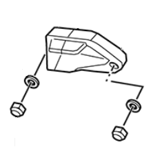
Installation Procedure
1. Install the 2 nuts securing the instrument panel to the turn signal brackets.
Tighten
Instrument Panel Nuts to 4 N•m (36 lb in)
2. Connect the C282 instrument panel harness connector.
3. Turn the handlebar fully right and install new zip ties in the same location as removed.
4. Install the instrument panel and turn signal assembly. Note: Ensure that ground C239 is attached.
5. Install the tank assembly.
6. Install the front fender.
7. Install the seat.
Version 1
| Torque settings for: Main Chassis Harness Replacement (11kW) | |
| Item | Torque Setting |
| Brushless Motor Controller Cable Bolt | 12 N•m (9 lb ft) |
| Seat Bolts | 22 N•m (16 lb ft) |
| Front Fender Bolts DS | 3 N•m (26 lb in) |
| ABS Fuse Holder Bolt | 3 N•m (26 lb in) |
| Fuse Holder Bolt | 1 N•m (12 lb in) |
| Front Fender Bolts S/SR/DSR | 11 N•m (8 lb ft) |
| Rear Tank Bolts | 5 N•m (48 lb in) |
| Front Fairing Screws | 2 N•m (18 lb in) |
| Front Tank Bolts | 4 N•m (36 lb in) |
| Instrument Panel Nuts | 4 N•m (36 lb in) |
 Show Torque Table
Caution: Always perform the High Voltage Discharging procedure prior to servicing any High Voltage component or connection. Proper procedures must be followed.
Required Tools
• 3mm hex wrench
• 5mm hex wrench
• Philips screwdriver
• 13mm wrench
Fastener Torques
Notice: Refer to Fastener Notice in General Information
• Brushless motor controller cable bolt 12 N•m (9 lb ft)
• Seat bolts 22 N•m (16 lb ft)
• ABS fuse holder bolt 3 N•m (26 lb in)
• Fuse holder bolt 1 N•m (12 lb in)
• Front fender bolts DS 3 N•m (26 lb in)
• Front fender bolts S/SR/DSR 11 N•m (8 lb ft)
• Rear tank bolts 5 N•m (48 lb in)
• Front fairing screws 2 N•m (18 lb in)
• Front tank bolts 4 N•m (36 lb in)
• Instrument panel nuts to 4 N•m (36 lb in)
Removal Procedure
Caution: Refer to High Voltage Caution in General Information
Note routing and location of harness and zip tie.

1. Disable the High Voltage system. Refer to High Voltage Discharging.
2. Remove the seat.
3. Remove the front fender (FRONT FENDER STREET TO WORK WITH SHOWA SUSPENSION BLACK #2, FRONT FENDER STREET TO WORK WITH SHOWA SUSPENSION YELLOW #2, FRONT FENDER STREET TO WORK WITH SHOWA SUSPENSION RED).
4. Remove the tank assembly (S TANK ASSEMBLY BLACK, S TANK ASSEMBLY YELLOW #2, DS TANK ASSEMBLY BLACK, DS TANK ASSEMBLY WHITE, DS TANK ASSEMBLY ORANGE #2, POWER TANK ASSY< SR RED, RED SR TANK (non power tank), MY15 PWER TANK ASSY> DS ORANGE, MY15 PWER TANK ASSY> DS WHITE, MY15 POWER TANK ASSY> S BLACK, MY15 POWER TANK ASSY> S YELLOW, MY15 POWER TANK ASSY> SR RED).
5. Disconnect the C90 controller connector.
6. Remove the controller cover retaining screw and cover (COVER MOTOR CONTROLLER GEN 4-4, BODYWORK MISC #6 CONTROLLER UN-SHIELDED COVER, #4 CONTROLLER COVER SHIELDED) from the controller.
7. Remove C89 motor controller ground eyelet.
8. Remove the fuse center screws.
9. Remove the instrument panel and turn signal assembly (TURN SIGNAL FR-RH RR-LH, TURN SIGNAL FR-LH RR-RH), HEADLIGHT MOUND RIGHT, HEADLIGHT MOUNT LEFT).
10. Remove the skid plate.
11. Disconnect C307 charger connector.
12. Disconnect C39 left rear turn signal connector.
13. Disconnect C40 right rear turn signal connector.
14. Disconnect C93 license plate connector.
15. Disconnect C303 tail light connector.
16. Disconnect C456 power pack connector.
17. Disconnect C134 AC charging ground harness connector.
18. Disconnect C1 and C2 main bike board connectors.
19. Disconnect C8 DC/DC converter connector.
20. Disconnect C14 motor harness connector.
21. Remove the C3 data link connector screws.
22. Disconnect C38 foot brake lamp switch connector.
23. Disconnect C459 throttle connector.
24. Disconnect C274 key switch connector.
25. Disconnect C282 instrument panel connector.
26. Disconnect C10 kickstand switch connector.
27. Disconnect C275 right handlebar control connector.
28. Disconnect C107 running light connector.
29. Disconnect C35 left handlebar control connector.
30. Disconnect C106 headlight connector.
31. Disconnect C33 right front turn signal connector.
32. Disconnect C34 left front turn signal connector.
33. Disconnect C45 hand brake switch connector.
34. Disconnect C32 horn connectors.
35. Disconnect C183/C184 inline harness connector.
36. Remove equipment grounds C238 and C239.
37. Remove the screw securing the D143 ABS fuse holder from the frame
Note harness routing prior to removal, this will aid in reassembly of the harness to the motorcycle.
38. Release all main wiring harness zip ties and hold down brackets and remove the harness.
Installation Procedure

1. Layout the wiring harness in the same location as removed on the frame.
2. Connect C32 horn connectors.
3. Connect the C45 hand brake switch connector.
4. Connect C34 left front turn signal connector.
5. Connect C33 right front turn signal connector.
6. Connect C106 headlight connector.
7. Connect C35 left handlebar control connector.
8. Connect C107 running light connector.
9. Connect C275 right handlebar control connector.
10. Connect C10 kickstand switch connector.
11. Connect C282 instrument panel connector.
12. Connect C274 key switch connector.
13. Connect C459 throttle connector.
14. Connect C38 foot brake lamp switch connector.
15. Install the C3 data link connector screws.
16. Connect C183/C184 inline connector.
17. Connect C14 motor harness connector.
18. Connect C8 DC/DC converter connector.
19. Connect C1 and C2 main bike board connectors.
20. Connect C134 AC charging ground harness connector.
21. Connect C456 power pack connector.
22. Connect C303 tail light connector.
23. Connect C93 license plate connector.
24. Connect C40 right rear turn signal connector.
25. Connect C39 left rear turn signal connector.
Note: Prior to connecting the charger connector coat the terminals with CP70 dielectric grease.
26. Connect C307 charger connector.
Notice: Refer to Fastener Notice in General Information
27. Install the skid plate.
28. Install the instrument panel and turn signal assembly. Ensure the C239 ground is installed.
Tighten
Instrument panel nuts to 4 N•m (36 lb in)
29. Install the fuse center screws.
Tighten
Fuse holder bolts to 1 N•m (12 lb in)
30. Install C89 brushless motor controller ground eyelet.
Tighten
Brushless motor controller cable bolt to 12 N•m (9 lb ft)
31. Install the controller cover and controller cover retaining screw.
32. Connect the C90 controller connector.
33. Install equipment grounds C238 and C239.
34. Install the screw securing the D143 ABS fuse holder onto the frame.
Tighten
ABS fuse holder bolts to 3 N•m (26 lb in)
35. Install zip ties in the same locations as removed.
36. Inspect harness routing to ensure that it is not in contact with any moving or sharp parts that could cause damage to the harness.
37. Install the tank assembly.
38. Install the front fender.
39. Install the seat.
Version 1
| Torque settings for: Main Chassis Harness Replacement (except 11kW) | |
| Item | Torque Setting |
| Brushless Motor Controller Cable Bolt | 12 N•m (9 lb ft) |
| Seat Bolts | 22 N•m (16 lb ft) |
| Front Fender Bolts DS | 3 N•m (24 lb in) |
| Front Fender Bolts S/SR/DSR | 11 N•m (8 lb ft) |
| Rear Tank Bolts | 5 N•m (48 lb in) |
| Front Fairing Screws | 2 N•m (18 lb in) |
| Front Tank Bolts | 4 N•m (36 lb in) |
| Instrument Panel Nuts | 4 N•m (36 lb in) |
| ABS Fuse Holder Bolt | 3 N•m (26 lb in) |
| Fuse Holder Bolt | 1 N•m (12 lb in) |
 Show Torque Table
Caution: Always perform the High Voltage Discharging procedure prior to servicing any High Voltage component or connection. Proper procedures must be followed.
Required Tools
• 3mm hex wrench
• 5mm hex wrench
• Philips screwdriver
• 13mm wrench
Fastener Torques
Notice: Refer to Fastener Notice in General Information
• Brushless motor controller cable bolt 12 N•m (9 lb ft)
• Seat bolts 22 N•m (16 lb ft)
• Front fender bolts DS 3 N•m (24 lb in)
• Front fender bolts S/SR/DSR 11 N•m (8 lb ft)
• Rear tank bolts 5 N•m (48 lb in)
• Front fairing screws 2 N•m (18 lb in)
• Front tank bolts 4 N•m (36 lb in)
• Instrument panel nuts to 4 N•m (36 lb in)
• ABS fuse holder bolt 3 N•m (26 lb in)
• Fuse holder bolt 1 N•m (12 lb in)
Removal Procedure
Caution: Refer to High Voltage Caution in General Information
Note routing and location of harness and zip tie.

1. Disable the High Voltage system. Refer to High Voltage Discharging.
2. Remove the seat.
3. Remove the front fender (FRONT FENDER STREET TO WORK WITH SHOWA SUSPENSION BLACK #2, FRONT FENDER STREET TO WORK WITH SHOWA SUSPENSION YELLOW #2, FRONT FENDER STREET TO WORK WITH SHOWA SUSPENSION RED).
4. Remove the tank assembly (S TANK ASSEMBLY BLACK, S TANK ASSEMBLY YELLOW #2, DS TANK ASSEMBLY BLACK, DS TANK ASSEMBLY WHITE, DS TANK ASSEMBLY ORANGE #2, POWER TANK ASSY< SR RED, RED SR TANK (non power tank), MY15 PWER TANK ASSY> DS ORANGE, MY15 PWER TANK ASSY> DS WHITE, MY15 POWER TANK ASSY> S BLACK, MY15 POWER TANK ASSY> S YELLOW, MY15 POWER TANK ASSY> SR RED).
5. Disconnect the C90 controller connector.
6. Remove the controller cover retaining screw and cover (COVER MOTOR CONTROLLER GEN 4-4, BODYWORK MISC #6 CONTROLLER UN-SHIELDED COVER, #4 CONTROLLER COVER SHIELDED) from the controller.
7. Remove C89 motor controller ground eyelet.
8. Remove the fuse center screws.
9. Remove the instrument panel and turn signal assembly (TURN SIGNAL FR-RH RR-LH, TURN SIGNAL FR-LH RR-RH), HEADLIGHT MOUND RIGHT, HEADLIGHT MOUNT LEFT).
10. Remove the skid plate.
11. Disconnect C307 charger connector.
12. Disconnect C39 left rear turn signal connector.
13. Disconnect C40 right rear turn signal connector.
14. Disconnect C93 license plate connector.
15. Disconnect C303 tail light connector.
16. Disconnect C456 power pack connector.
17. Disconnect C134 AC charging ground harness connector.
18. Disconnect C1 and C2 main bike board connectors.
19. Disconnect C8 DC/DC converter connector.
20. Disconnect C14 motor harness connector.
21. Disconnect C142/C431 inline connector.
22. Remove the C3 data link connector screws.
23. Disconnect C38 foot brake lamp switch connector.
24. Disconnect C459 throttle connector.
25. Disconnect C274 key switch connector.
26. Disconnect C282 instrument panel connector.
27. Disconnect C10 kickstand switch connector.
28. Disconnect C275 right handlebar control connector.
29. Disconnect C107 running light connector.
30. Disconnect C35 left handlebar control connector.
31. Disconnect C106 headlight connector.
32. Disconnect C33 right front turn signal connector.
33. Disconnect C34 left front turn signal connector.
34. Disconnect C45 hand brake switch connector.
35. Disconnect C32 horn connectors.
36. Disconnect C183/C184 inline harness connector.
37. Remove equipment grounds C238 and C239.
38. Disconnect C457/C472 inline harness connector.
39. Remove the screw securing the D143 ABS fuse holder from the frame
Note harness routing prior to removal, this will aid in reassembly of the harness to the motorcycle.
40. Release all main wiring harness zip ties and hold down brackets and remove the harness.
Installation Procedure

1. Layout the wiring harness in the same location as removed on the frame.
2. Connect C32 horn connectors.
3. Connect the C45 hand brake switch connector.
4. Connect C34 left front turn signal connector.
5. Connect C33 right front turn signal connector.
6. Connect C106 headlight connector.
7. Connect C35 left handlebar control connector.
8. Connect C107 running light connector.
9. Connect C275 right handlebar control connector.
10. Connect C10 kickstand switch connector.
11. Connect C282 instrument panel connector.
12. Connect C274 key switch connector.
13. Connect C459 throttle connector.
14. Connect C38 foot brake lamp switch connector.
15. Install the C3 data link connector screws.
16. Connect C183/C184 inline connector.
17. Connect C14 motor harness connector.
18. Connect C8 DC/DC converter connector.
19. Connect C1 and C2 main bike board connectors.
20. Connect C134 AC charging ground harness connector.
21. Connect C456 power pack connector.
22. Connect C303 tail light connector.
23. Connect C93 license plate connector.
24. Connect C40 right rear turn signal connector.
25. Connect C39 left rear turn signal connector.
Note: Prior to connecting the charger connectors coat the terminals with CP70 dielectric grease.
26. Connect C307 charger connector.
Notice: Refer to Fastener Notice in General Information
27. Install the skid plate.
28. Install the instrument panel and turn signal assembly. Ensure the C239 ground is installed.
Tighten
Instrument panel nuts to 4 N•m (36 lb in)
29. Install the fuse center screws.
Tighten
Fuse holder bolts to 1 N•m (12 lb in)
30. Install C89 brushless motor controller ground eyelet.
Tighten
Brushless motor controller cable bolt to 12 N•m (9 lb ft)
31. Install the controller cover and controller cover retaining screw.
32. Connect the C90 controller connector.
33. Connect the C142/C431 inline connector.
34. Install equipment grounds C238 and C239.
35. Connect C457/C472 inline harness connector
36. Install the screw securing the D143 ABS fuse holder onto the frame.
Tighten
ABS fuse holder bolts to 3 N•m (26 lb in)
37. Install zip ties in the same locations as removed.
38. Inspect harness routing to ensure that it is not in contact with any moving or sharp parts that could cause damage to the harness.
39. Install the tank assembly.
40. Install the front fender.
41. Install the seat.
Version 1
| Torque settings for: Power Harness Replacement (Power Tank) | |
| Item | Torque Setting |
| Seat Bolts | 22 N•m (16 lb ft) |
| Rear Tank Bolts | 5 N•m (48 lb in) |
| Front Fender Bolts DS | 3 N•m (24 lb in) |
| Front Fender Bolts S/SR/DSR | 11 N•m (8 lb ft) |
| Front Fairing Screws | 2 N•m (18 lb in) |
| Front Tank Bolts | 4 N•m (35 lb in) |
 Show Torque Table
Caution: Always perform the High Voltage Discharging procedure prior to servicing any High Voltage component or connection. Proper procedures must be followed.
Required Tools
• 3mm hex wrench
• 5mm hex wrench
• Philips screwdriver
• 15mm wrench
Fastener Torques
Notice: Refer to Fastener Notice in General Information
• Seat bolts 22 N•m (16 lb ft)
• Rear tank bolts 5 N•m (48 lb in)
• Front fender bolts DS 3 N•m (24 lb in)
• Front fender bolts S/SR/DSR 11 N•m (8 lb ft)
• Front fairing screws 2 N•m (18 lb in)
• Front tank bolts 4 N•m (35 lb in)
Removal Procedure
Caution: Refer to High Voltage Caution in General Information
Note routing and location of harness and zip ties.
1. Discharge the High Voltage system. Refer to High Voltage Discharging.
2. Remove the seat.
3. Remove the front fender (FRONT FENDER STREET TO WORK WITH SHOWA SUSPENSION BLACK #2, FRONT FENDER STREET TO WORK WITH SHOWA SUSPENSION YELLOW #2, FRONT FENDER STREET TO WORK WITH SHOWA SUSPENSION RED).
4. Remove the tank assembly (DS TANK ASSEMBLY BLACK, DS TANK ASSEMBLY WHITE, POWER TANK ASSY< SR RED, MY15 PWER TANK ASSY> DS ORANGE, MY15 PWER TANK ASSY> DS WHITE, MY15 POWER TANK ASSY> S BLACK, MY15 POWER TANK ASSY> S YELLOW, MY15 POWER TANK ASSY> SR RED)
5. Remove the controller cover retaining screw and cover (COVER MOTOR CONTROLLER GEN 4-4, BODYWORK MISC #6 CONTROLLER UN-SHIELDED COVER, #4 CONTROLLER COVER SHIELDED) from the controller.
6. Remove the brushless motor controller cable bolts and cables (C368 and C369).
7. Disconnect C367 power pack connector, and remove the C366 connector from C367. Note: C366 is part of the Power Tank Signal Harness.
8. Remove the harness from the frame.
Installation Procedure
1. Lay out the wiring harness in the same location as removed on the frame.
2. Insert the C366 connector into the C367 connector and connect the C367 power pack connector.
Notice: Refer to Fastener Notice in General Information.
3. Install the controller cable bolts and cables (C368 and C369).onto the brushless motor controller.
Tighten
Motor controller cable bolts to 12 N•m (9 lb ft)
4. Install the controller cover and retaining screw retaining screw.
5. Install zip ties in the same locations as removed.
6. Inspect harness routing to ensure that it is not in contact with any moving or sharp parts that could cause damage to the harness.
7. Install the tank assembly.
8. Install the front fender.
9. Install the seat.
Version 1
| Torque settings for: Signal Harness Replacement (Power Tank) | |
| Item | Torque Setting |
| Seat Bolts | 22 N•m (16 lb ft) |
| Rear Tank Bolts | 5 N•m (48 lb in) |
| Front Fender Bolts DS | 3 N•m (24 lb in) |
| Front Fender Bolts S/SR/DSR | 11 N•m (8 lb ft) |
| Front Fairing Screws | 2 N•m (18 lb in) |
| Front Tank Bolts | 4 N•m (35 lb in) |
 Show Torque Table
Caution: Always perform the High Voltage Discharging procedure prior to servicing any High Voltage component or connection. Proper procedures must be followed.
Required Tools
• 3mm hex wrench
• 5mm hex wrench
• Philips screwdriver
Fastener Torques
Notice: Refer to Fastener Notice in General Information.
• Seat bolts 22 N•m (16 lb ft)
• Rear tank bolts 5 N•m (48 lb in)
• Front fender bolts DS 3 N•m (24 lb in)
• Front fender bolts S/SR/DSR 11 N•m (8 lb ft)
• Front fairing screws 2 N•m (18 lb in)
• Front tank bolts 4 N•m (35 lb in)
Removal Procedure
Caution: Refer to High Voltage Caution in General Information.
Note routing and location of harness and zip ties.1. Discharge the High Voltage system. Refer to High Voltage Discharging.
2. Remove the seat.
3. Remove the front fender (FRONT FENDER STREET TO WORK WITH SHOWA SUSPENSION BLACK #2, FRONT FENDER STREET TO WORK WITH SHOWA SUSPENSION YELLOW #2, FRONT FENDER STREET TO WORK WITH SHOWA SUSPENSION RED).
4. Remove the tank assembly (DS TANK ASSEMBLY BLACK, DS TANK ASSEMBLY WHITE, POWER TANK ASSY< SR RED, MY15 PWER TANK ASSY> DS ORANGE, MY15 PWER TANK ASSY> DS WHITE, MY15 POWER TANK ASSY> S BLACK, MY15 POWER TANK ASSY> S YELLOW, MY15 POWER TANK ASSY> SR RED).
5. Disconnect C367 power pack connector, and remove the C366 connector from C367. Note C367 is part of the Power Tank Power Harness.
6. Disconnect the C500/C501 Chassis Harness to Power Tank Harness inline connector.
7. Remove the harness from the frame.
Installation Procedure
1. Lay out the wiring harness in the same location as removed on the frame.
2. Insert the C366 connector into the C367 connector and connect the C367 power pack connector.
3. Connect the C500/C501 Chassis Harness to Power Tank Harness inline connector.
4. Install zip ties in the same locations as removed.
5. Inspect harness routing to ensure that it is not in contact with any moving or sharp parts that could cause damage to the harness.
6. Install the tank assembly.
7. Install the front fender.
8. Install the seat.
Version 1
The 12 volt fuse center is located under the seat.

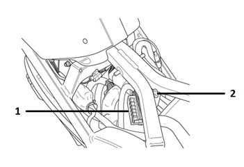
Legend:
1. Fuse Center
2. ABS 12 volt fuse
To access the 12 volt fuse center:
1. Remove two bolts securing the seat to the motorcycle frame.
2. Pull the seat rearward to gain access to the fuse center.
3. Squeeze the tabs (A) on the fuse center to remove the cover.
4. Replace the fuse(s).

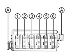
|
Fuse
|
Rating
|
Circuits Controlled
|
|
1
|
5 A
|
ABS-4 Key
|
|
2
|
10 A
|
ABS-9 Valve
|
|
3
|
10 A
|
Headlight
|
|
4
|
10 A
|
Accessory
|
| 5 | 10 A | Flash Lights, Turn Signals, Horn, Brake/Tail Light |
| 6 | 5 A | Dash, Running Lights |
To access the ABS 12 volt fuse:
1. Remove two bolts securing the seat to the motorcycle frame.
2. Pull the seat rearward to gain access to the fuse.
3. Gently pull the tab (A) away from the red cap to release the fuse holder and pull upwards.
4. Replace the fuse.

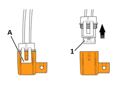
|
Fuse
|
Rating
|
Circuits Controlled
|
|
1
|
25 A
|
ABS-18 Motor
|
Power Pack
ZF7.2

To access the ZF7.2 power pack fuse:
1. Remove the bolt (1) securing the fuse cover.
2. Remove the fuse cover (2) to access the fuse.
3. Unscrew the fuse's cover (3).
4. Replace the fuse.
5. Screw on the fuse's cover and install the fuse main cover. Torque the bolt to 1.3 N•m (11.5 lb in).
Version 1
High Voltage Fuses
ZF14.4
ZF14.4 illustrated. ZF7.2 similar except for fuse 1.


To access the high voltage fuses:
1. Remove the two bolts securing the seat to the motorcycle frame.
2. Pull the seat rearward to gain access to the fuses.
3. Pull back sheathing to access fuse holders (if necessary).
4. Unscrew the fuse’s cover (1, 2, and 3).
5. Replace the fuse.
|
Fuse
|
Rating
|
Circuits Controlled
|
|
1
|
SPT3 15 A
|
Low Power B+
|
|
2
|
ABC 4 A
|
Main Bike Board/Controller
|
|
3
|
ABC 4 A
|
DC/DC Converter
|
|
4
|
100 A
|
Charge Fuse (in-line)
|
Version 1

Legend:
A. Adjust button (ADJ)
B. Select Button (SEL)
C. Charge indicator
D. Remaining charge time control
E. Clock
F. Speedometer
G. Odometer
H. Performance modes
I. Output meter
J. Regen meter
K. Displays A&B
L. Bluetooth® Indicator
Functions

The displays on the dash can be customized to your personal preferences by using the ADJ (Adjust) and SEL (Select) buttons.
A. Adjust Button (ADJ)
By momentarily pressing or holding the ADJ button you can reset fields and toggle through the trip menus and display options.
B. Select Button (SEL)
By momentarily pressing or holding the SEL button you can reset or select fields in Display A and Display B, change the time, and change the display units. Note: Once a feature is selected, it will stop flashing after 15 seconds if no further button press is detected, and the dash will return to its normal operating mode.
C. Charge Indicator
This indicator and readout displays the amount of energy remaining in the power pack, similar to the fuel gauge on a gasoline powered vehicle.
D. Remaining Charge Time Indicator
This area displays the amount of time left for the power pack to reach full charge.
E. Clock
The clock displays time in standard (AM/PM) or 24 hour mode.
F. Speedometer
The speedometer is a digital display in either kilometers per hour (km/h) or miles per hour (mph).
G. Odometer
The odometer displays the total distance the motorcycle has been ridden in kilometers or miles.
H. Performance Modes
This area displays which performance riding mode (ECO, SPORT, and CUSTOM) has been selected by the rider using the performance level mode button located on the right handlebar control assembly.
I. Output Meter
The output meter indicates the amount of torque applied to the rear wheel and the Power (energy) being used while riding.
J. Regen Meter
The regenerative (REGEN) meter indicates the amount of torque on the rear wheel and the Power (energy) feeding back into the battery of the motorcycle during the regenerative braking process.
K. Displays A&B
Displays A&B can be customized to display functions which include Trip Odometers, Range, Errors, RPM, Trip Average, Lifetime Average, and Temperature. All are accessible by using the ADJ and SEL buttons.
L. Bluetooth® Indicator
This indicator displays when an active Bluetooth® equipped smartphone is paired with the motorcycle.
Version 1

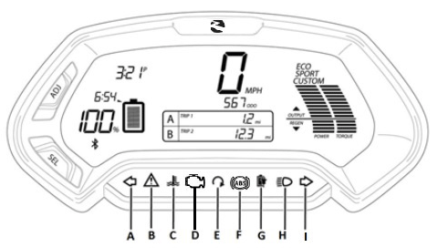
Legend:
A. Left Turn Signal Indicator
B. System Warning
C. Temperature
D. Check Engine Light
E. Armed
F. ABS (Anti-Lock Brake System)
G. Charging
H. High Beam
I. Right Turn Signal Indicator
Functions
A. Left and I. Right Turn Signal Indicators
An arrow on the lower dash flashes green in the same direction as selected by the turn signal switch. This arrow remains on until the turn signal request has been canceled.
B. System Warning
If a fault has been detected, count the number of times the red LED flashes.
C. Temperature
• A flashing light indicates that one or more of the powertrain components are approaching their temperature limit. Performance will not be affected.
• If the light illuminates continuously, it indicates that one or more of the powertrain components have exceeded their temperature limit. Performance will be reduced until the component(s) have cooled sufficiently
D. Check Engine Light
Indicates the motorcycle has detected an error, causing it to enter into a state of permanent torque reduction. This light will be accompanied by a dash error code.
E. Armed
Indicates the motorcycle is live or ready to move if the throttle is actuated.
F. ABS
The indicator illuminates when the key is in the ON position. The light will extinguish when the motorcycle exceeds 3 mph (5 km/h). Unless there is a fault, the indicator will stay off until the key is cycled off and back to the ON position again.
G. Charging
This indicator flashes slowly when the motorcycle is accepting a charge, and rapidly when a charging error is detected. The indicator is solid green when the battery is completely charged.
H. High Beam
When the headlight high beam is on, this indicator illuminates blue, and remains on until the high beam is turned off.

Display A
To select Display A with the dash in its normal operating mode, momentarily press the SEL button once. Press the ADJ button to toggle through the following fields:
• Trip 1 Odometer - Displays individual trip mileage and is reset by pressing and holding the ADJ button for 2 seconds. Note: Trip 1 is reset each time the battery is recharged to 100%.
• Range - Displays remaining battery power based on learned riding style and usage.
• Errors - Displays 4-digit error codes for dealer use.
• RPM - Displays motor RPM.
Display B
To select Display B with the dash in its normal operating mode, momentarily press the SEL button twice. Press the ADJ button to toggle through the following fields:
• Trip 2 Odometer - Displays individual trip mileage and is reset by pressing and holding the ADJ button for 2 seconds.
• Trip AV - Displays the average energy usage during duration of Trip 1 in watt hours (Wh), per mile (mi), or kilometer (km), depending on the currently selected display unit.
Note: The Trip AV is reset each time the battery is recharged to 100%
• Temp - Displays the temperature of the motor, battery, and controller in Fahrenheit (F) or Celsius (C).
Note: The temperature may not read accurately during the first 5 miles of a ride while the application is calibrating itself.
• Life AV - Displays the average energy usage over the life of the motorcycle in watt hours (Wh), per mile (mi), or kilometer (km), depending on the currently selected display unit.
Setting the Clock

To set the clock with the dash in its normal operating mode, press and hold the SEL button for 5 seconds, then momentarily press the SEL button once more. The clock display will start to flash.
• Hours - Press and release the ADJ button to increase the hour setting.
• Minutes - Press and release the SEL button once to select the minute display, then press and release the ADJ button to increase the minute setting.
• Standard or 24 Hour Mode - Press and release the SEL button to select the time format, then press the ADJ button to select P (am/pm mode) or 24:00 (24 hour mode).
Unit Display – Speed

To change the units that speed is shown in:
1. With the dash in its normal operating mode press and hold the SEL button for 5 seconds.
2. Momentarily press the ADJ button to select English (MPH) or metric (km/h).
3. Momentarily press the SEL button to return to normal operating mode.
Unit Display – Temperature

To change the units that the temperature display is shown:
1. With the dash in its normal operating mode press and hold the SEL button for 5 seconds.
2. Momentarily press the SEL button 4 times, the Temp icon on the lower dash will start to flash.
3. Press the ADJ button to toggle between F or C on the display.
4. Momentarily press the SEL button to return to normal operating mode.
The instrument panel cluster (IPC) LCD screen is powered by 5 volts the backlight is powered by 12 volts.
Version 1
|
Application
|
Specification
|
|
|
Metric
|
English
|
|
| Brake Pedal Pivot Bolt* |
46 N•m
|
34 lb ft
|
| Brushless Motor Controller Bolts | 26 N•m | 19 lb ft |
| Power Pack Bolts | 27 N•m | 20 lb ft |
| Motor Stop Switch Screws | 3 N•m | 24 lb in |
| Brushless Motor Controller Heat Sink Bolts | 7 N•m | 5 lb ft |
| Brushless Motor Controller Heat Sink (size 6) Bolts | 11 N•m | 8 lb ft |
| Brushless Motor Controller Cable Bolts | 12 N•m | 9 lb ft |
|
DC/DC Converter Bolts
|
11 N•m
|
8 lb ft
|
|
Power Pack Charger Screws
|
1.4 N•m
|
12 lb in
|
| Module Bracket to Frame Bolts |
7 N•m
|
60 lb in
|
| Left Side Motor Bolts** |
27 N•m
|
20 lb ft
|
| Right Side Motor Bolts |
27 N•m
|
20 lb ft
|
| Upper Frame/Fuse Center Brace Nuts | 9 N•m | 7 lb ft |
| Main Bike Board (MBB) Bolts | 1.4 N•m | 12 lb in |
| Rear Master Cylinder Bolts* | 12 N•m | 9 lb ft |
| Seat Bolts | 22 N•m | 16 lb ft |
| Skid Plate Bolts | 9 N•m | 8 lb ft |
|
Rear Tank Bolts
|
5 N•m
|
48 lb in
|
| Front Fairing Screws |
2 N•m |
18 lb in |
| Front Tank Bolts |
4 N•m |
35 lb in |
*Use LOCTITE® 242® (or equivalent)
**Use Polylube 1000TM (or equivalent)
Version 1
| Torque settings for: Brushless Motor Controller Replacement | |
| Item | Torque Setting |
| Seat Bolts | 22 N•m (16 lb ft) |
| Brushless Motor Controller Bolts | 26 N•m (19 lb ft) |
| Brushless Motor Controller Cable Bolts | 12 N•m (9 lb ft) |
 Show Torque Table
Caution: Always perform the High Voltage Disabling procedure prior to servicing any High Voltage component or connection. Proper procedures must be followed!
Important: Always ensure that the controller is commissioned using Zero motorcycle programming tools prior to operation.
Required Tools
• 8mm wrench
• 13mm wrench
• 3mm hex wrench
• 6mm hex wrench
• 5mm hex wrench
• Philips screwdriver
• PN 85-05665 Controller Discharge Tool
Fastener Torques
Notice: Refer to Fastener Notice in General Information
• Seat bolts 22 N•m (16 lb ft)
• Brushless motor controller bolts 26 N•m (19 lb ft)
• Brushless motor controller cable bolts to 12 N•m (9 lb ft)
Removal Procedure
Caution: Refer to High Voltage Caution in General Information
1. Discharge the high voltage system. Refer to High Voltage Disabling.
2. Remove the seat (1).
3. Remove the rear shock (DS SHOCK 40MM, LONGBRICK, DS SHOCK 40MM, DS SHOCK 40MM, S SHOCK 40MM 2, S SHOCK 40MM).
4. Remove the left side trim screw (2) and the right side trim screw.

5. Remove the 4 body fasteners (2) and remove the rubber trim (2).

6. Disconnect the C90 11 kW or C90 except 11 kW controller connector.
7. Remove the controller cover retaining screw and cover (#4 CONTROLLER COVER, BODYWORK MISC #6 CONTROLLER UN-SHIELDED COVER) from the controller.
Note: Mark the cable location and orientation prior to removal.
8. Remove the motor cable bolts (1) from the motor controller.
9. Remove the power pack cables (2) from the motor controller.
Size 4:

Size 6:

10. Remove the front controller bolts (1).

11. Remove the rear controller bolts (1) spacers (size 4 only) and remove the controller (CONTROLLER, SIZE 4 GEN 4.5 SEVCON, CONTROLLER, SIZE 6 GEN 4.5 SEVCON).
12. Remove the heat sink (HEATSINK #4 CONTROLLER SDS, R CONTROLLER HEATSINK) from the controller if required. Refer to Brushless Motor Controller Heat Sink Replacement.
Size 4:

Size 6:

Installation Procedure
1. Install the heat sink onto the controller if required. Refer to Brushless Motor Controller Heat Sink Replacement.
2. Place the controller into position and loosely install the front bolts (1).

3. Loosely install the rear controller bolts (1).
Size 4:

Size 6:

Notice: Refer to Fastener Notice in General Information
4. Tighten all four controller bolts.
Tighten
Brushless motor controller bolts to 26 N•m (19 lb ft)
5. Install the cables (1, 2) to the controller in the same locations as removed and tighten.
Tighten
Brushless motor controller cable bolts to 12 N•m (9 lb ft)
Size 4:

Size 6:

6. Install the controller cover and cover retaining screw.
7. Install the rear shock.
8. Connect the C90 controller connector.
9. Install the rubber trim (2) and body fasteners (1).

10. Install the left side trim nut and bolt (2), and the right side trim nut and bolt.
11. Install the seat (1).
12. Program the new controller. Refer to New Motor or Controller Commissioning and Timing Procedure.

Version 1
| Torque settings for: Brushless Motor Controller Heat Sink Replacement | |
| Item | Torque Setting |
| Seat Bolts | 22 N•m (16 lb ft) |
| Brushless Motor Controller Heat Sink Bolts | 7 N•m (5 lb ft) |
| Brushless Motor Controller Heat Sink (size 6) Bolts | 11 N•m (8 lb ft) |
 Show Torque Table
Note: Size 4 shown, size 6 similar.
Required Tools
• 10mm hex wrench
• 13mm hex wrench
• 4mm hex wrench
• 6mm hex wrench
• 8mm hex wrench
Fastener Torques
Notice: Refer to Fastener Notice in General Information.
• Seat bolts 22 N•m (16 lb ft)
• Brushless motor controller heat sink bolts 7 N•m (5 lb ft)
• Brushless motor controller heat sink (size 6) bolts 11 N•m (8 lb ft)
Removal Procedure
1. Remove the brushless motor controller (CONTROLLER, SIZE 4 GEN 4.5 SEVCON, CONTROLLER, SIZE 6 GEN 4.5 SEVCON). Refer to Brushless Motor Controller Replacement.
2. Remove the heat sink bolts (1), and separate the heat sink (HEATSINK #4 CONTROLLER SDS, R CONTROLLER HEATSINK) from the brushless motor controller.

Installation Procedure
Important: A layer of thermal grease (such as Dow Corning® 340) MUST be applied as described below, before bolting the brushless motor controller to the heat sink.
1. Clean the mounting surface of the brushless motor controller of any old thermo grease.
2. Apply the thermal grease to both the brushless motor controller and the heat sink using a small soft paint roller to ensure an even spread of thermal compound. The most appropriate thickness will look white but with a grayish color still showing through from the controller base or heat sink. Note that too little thermal compound will not fill all gaps of the contact surfaces, but too much thermal compound may prevent the gap from closing up when tightening.
3. Place the heat sink onto the brushless motor controller and rub both surfaces together. This will help transfer the thermal compound between the two surfaces.
Notice: Refer to Fastener Notice in General Information.
4. Install the heat sink bolts (1).
Tighten
Brushless motor controller heat sink bolts to 7 N•m (5 lb ft)
Brushless motor controller heat sink (size 6) bolts 11 N•m (8 lb ft)
5. Install the brushless motor controller. Refer to Brushless Motor Controller Replacement.

Version 1
| Torque settings for: DC/DC Converter Replacement | |
| Item | Torque Setting |
| Seat Bolts | 22 N•m (16 lb ft) |
| Rear Tank Bolts | 5 N•m (48 lb in) |
| Front Fairing Screws | 2 N•m (18 lb in) |
| Front Tank Bolts | 4 N•m (35 lb in) |
| Front Fender Bolts DS | 3 N•m (24 lb in) |
| Front Fender Bolts S/SR | 11 N•m (8 lb ft) |
 Show Torque Table
DC/DC Converter Replacement
Caution: Always perform the High Voltage Discharging procedure prior to servicing any High Voltage component or connection. Proper procedures must be followed!
Required Tools
• 3mm hex wrench
• 4mm hex wrench
• 5mm hex wrench
• 10mm wrench
• Philips screwdriver
• PN 85-05665 Controller Discharge Tool
Fastener Torques
Notice: Refer to Fastener Notice in General Information
• Seat bolts 22 N•m (16 lb ft)
• Rear tank bolts 5 N•m (48 lb in)
• Front fairing screws 2 N•m (18 lb in)
• Front tank bolts 4 N•m (35 lb in)
• Main bike board bolts 1.4 N•m (12 lb in)
• DC/DC converter bolts 11 N•m (8 lb ft)
• Front fender bolts DS 3 N•m (24 lb in)
• Front fender bolts S/SR/DSR 11 N•m (8 lb ft)
• Module bracket bolts 7 N•m (60 lb in)
• Upper frame/fuse center nuts 9 N•m (7 lb ft)
Caution: Refer to High Voltage Caution in General Information.
Note: Mark the location and routing of all wires and cables prior to removal.
Removal Procedure
1. Discharge the high voltage system. Refer to High Voltage Discharging.
2. Remove the seat.
3. Remove the low voltage B+ fuse (1)
• Remove the fuse cover hex screw.
• Remove the fuse cover.

4. Remove the front fender (PAINTED S/SR FRONT FENDER YELLOW #3, PAINTED S/SR FRONT FENDER WHITE #3, PAINTED S/SR FRONT FENDER BLACK #3, PAINTED S/SR FRONT FENDER RED #3, FRONT FENDER DIRT BRAKE LINE HOLE).
5. Remove the tank assembly (PAINTED S YELLOW POWER TANK ASSEMBLY , PAINTED S WHITE POWER TANK ASSEMBLY , PAINTED S BLACK POWER TANK ASSEMBLY , PAINTED S RED POWER TANK ASSEMBLY , PAINTED DS ORANGE POWER TANK ASSEMBLY , PAINTED DS WHITE POWER TANK ASSEMBLY , PAINTED DS BLACK POWER TANK ASSEMBLY , PAINTED DS GRAPHITE POWER TANK ASSEMBLY , PAINTED SR YELLOW CHARGE TANK ASSEMBLY, PAINTED SR WHITE CHARGE TANK ASSEMBLY , PAINTED SR BLACK CHARGE TANK ASSEMBLY, PAINTED SR RED CHARGE TANK ASSEMBLY , PAINTED S YELLOW CHARGE TANK ASSEMBLY , PAINTED S WHITE CHARGE TANK ASSEMBLY, PAINTED S BLACK CHARGE TANK ASSEMBLY, PAINTED S RED CHARGE TANK ASSEMBLY, PAINTED DS WHITE CHARGE TANK ASSEMBLY , PAINTED DS ORANGE CHARGE TANK ASSEMBLY , PAINTED DS BLACK CHARGE TANK ASSEMBLY, PAINTED DS GRAPHITE CHARGE TANK ASSEMBLY , PAINTED DSR WHITE CHARGE TANK ASSEMBLY, PAINTED DSR ORANGE CHARGE TANK ASSEMBLY, PAINTED DSR BLACK CHARGE TANK ASSEMBLY , PAINTED DSR GRAPHITE CHARGE TANK ASSEMBLY, PAINTED SR YELLOW POWER TANK ASSEMBLY, PAINTED SR WHITE POWER TANK ASSEMBLY , PAINTED SR BLACK POWER TANK ASSEMBLY, PAINTED SR RED POWER TANK ASSEMBLY, PAINTED DSR WHITE POWER TANK ASSEMBLY, PAINTED DSR ORANGE POWER TANK ASSEMBLY, PAINTED DSR BLACK POWER TANK ASSEMBLY, PAINTED DSR GRAPHITE POWER TANK ASSEMBLY, PAINTED S YELLOW TANK TRUNK ASSEMBLY , PAINTED S WHITE TANK TRUNK ASSEMBLY, PAINTED S BLACK TANK TRUNK ASSEMBLY , PAINTED S RED TANK TRUNK ASSEMBLY, PAINTED DS WHITE TANK TRUNK ASSEMBLY , PAINTED DS ORANGE TANK TRUNK ASSEMBLY , PAINTED DS BLACK TANK TRUNK ASSEMBLY , PAINTED DS GRAPHITE TANK TRUNK ASSEMBLY , PAINTED SR YELLOW TANK TRUNK ASSEMBLY, PAINTED SR WHITE TANK TRUNK ASSEMBLY, PAINTED SR BLACK TANK TRUNK ASSEMBLY, PAINTED SR RED TANK TRUNK ASSEMBLY , PAINTED DSR WHITE TANK TRUNK ASSEMBLY , PAINTED DSR ORANGE TANK TRUNK ASSEMBLY, PAINTED DSR BLACK TANK TRUNK ASSEMBLY , PAINTED DSR GRAPHITE TANK TRUNK ASSEMBLY ).
6. Remove the upper frame/fuse center bracket (1), and set aside. Note: Leave the wiring connected to the fuse center.

7. Disconnect the C1 11 kW or C1 except 11 kW and C2 11 kW or C2 except 11 kW MBB harness connectors.
8. Remove the brushless motor controller cover retaining screws and cover (#4 CONTROLLER COVER, BODYWORK MISC #6 CONTROLLER UN-SHIELDED COVER). Mark the location of brushless motor controller cable bolts prior to removal.
9. Remove the controller cable bolts (1,2) and remove the cables.
Size 4:

Size 6:

10. Remove the rear ABS harness mounting bracket from the bottom of the module bracket.
11. Remove the screws securing the C3 11 kW or C3 except 11 kW data link connector from the bottom of the module bracket.
12. Remove the screws securing the C50 11 kW or C50 except 11 kW quick charge connector from the bottom of the module bracket.
13. Disconnect the C14 11 kW or C14 except 11 kW Motor Harness to the Chassis Harness connector.
14. Remove the 2 left side module bracket bolts (1) and the right side module bracket bolts.

15. Carefully moving harnesses out of the way, pull the module bracket up enough to disconnect the C08 DC/DC converter harness connector.
16. Remove the 2 bolts (1) securing the DC/DC Converter to the module bracket and remove the DC/DC Converter.

Installation Procedure
Notice: Refer to Fastener Notice in General Information
1. Install the DC/DC converter onto the module bracket and install the nuts (1).
Tighten
DC/DC converter bolts to 11 N•m (8 lb ft)

2. Slide the module bracket into position and connect the C08 DC/DC converter harness connector.
3. Install the 2 left side module bracket bolts (1) and the right side module bracket bolts.
Tighten
Module bracket bolts to 7 N•m (60 lb in)

4. Install the screws securing the C50 quick charge connector onto the bottom of the module bracket.
5. Install the screws securing the C3 data link connector onto the bottom of the module bracket.
6. Install the rear ABS harness mounting bracket onto the bottom of the module bracket.
7. Connect the C14 Motor Harness to the Chassis Harness connector.
Notice: Refer to Fastener Notice in General Information
8. Install the cables and bolts (1,2) in the same locations and routings as removed.
Tighten
Brushless motor controller cable bolts to 12 N•m (9 lb ft)
Size 4:

Size 6:

9. Install the controller cover and cover retaining screws.
10. Connect the C90 Brushless motor controller connector.
11. Connect the C01 and C02 MBB harness connectors.
12. Install the upper frame/fuse center bracket (1), and tighten the nuts.
Tighten
Upper frame/fuse center bracket nuts to 9 N•m (7 lb ft)

13. Install the tank assembly.
14. Install the front fender.
15. Install the low voltage B+ fuse (1)
• Install the fuse cover
• Install the fuse cover bolt

16. Install the seat.
Version 1
| Torque settings for: Ignition Switch/Lock Cylinder Replacement | |
| Item | Torque Setting |
| Seat Bolts | 22 N•m (16 lb ft) |
| Rear Tank Bolts | 5 N•m (48 lb in) |
| Front Fairing Screws | 2 N•m (18 lb in) |
| Front Tank Bolts | 4 N•m (35 lb in) |
| Front Fender Bolts DS | 3 N•m (24 lb in) |
| Front Fender Bolts S/SR | 11 N•m (8 lb ft) |
| Headlight Bolts | 5 N•m (48 lb in) |
 Show Torque Table
Required Tools
• Philips screwdriver
• 3mm Hex wrench
• 4mm Hex wrench
• 5mm Hex wrench
• 10mm hex wrench
Fastener Torques
Notice: Refer to Fastener Notice in General Information
• Seat bolts 22 N•m (16 lb ft)
• Rear tank bolts 5 N•m (48 lb in)
• Headlight bolts 5 N•m (48 lb in)
• Front fairing screws 2 N•m (18 lb in)
• Front fender bolts DS 3 N•m (24 lb in)
• Front fender bolts S/SR/DSR 11 N•m (8 lb ft)
• Front tank bolts 4 N•m (35 lb in)
Removal Procedure
Note: The ignition switch and lock cylinder are replaced as a assembly.
Note: Duplicate keys can be made by using the 5-digit key code number. This number is located on a tag that accompanies the original keys.
1. Remove the key from the key switch.
2. Remove the headlight assembly.
3. Remove the instrument panel and turn signal assembly (TURN SIGNAL FR-RH RR-LH, TURN SIGNAL FR-LH RR-RH, HEADLIGHT MOUNT RIGHT, HEADLIGHT MOUNT LEFT).
4. Remove the two screws (1) securing the ignition switch to the lock cylinder. This will provided additional clearance for removal of the breakaway bolts.
5. Remove the seat.
6. Remove the front fender (PAINTED S/SR FRONT FENDER YELLOW #3, PAINTED S/SR FRONT FENDER WHITE #3, PAINTED S/SR FRONT FENDER BLACK #3, PAINTED S/SR FRONT FENDER RED #3, FRONT FENDER DIRT BRAKE LINE HOLE).
7. Remove the tank assembly (PAINTED S YELLOW POWER TANK ASSEMBLY , PAINTED S WHITE POWER TANK ASSEMBLY , PAINTED S BLACK POWER TANK ASSEMBLY , PAINTED S RED POWER TANK ASSEMBLY , PAINTED DS ORANGE POWER TANK ASSEMBLY , PAINTED DS WHITE POWER TANK ASSEMBLY , PAINTED DS BLACK POWER TANK ASSEMBLY , PAINTED DS GRAPHITE POWER TANK ASSEMBLY , PAINTED SR YELLOW CHARGE TANK ASSEMBLY, PAINTED SR WHITE CHARGE TANK ASSEMBLY , PAINTED SR BLACK CHARGE TANK ASSEMBLY, PAINTED SR RED CHARGE TANK ASSEMBLY , PAINTED S YELLOW CHARGE TANK ASSEMBLY , PAINTED S WHITE CHARGE TANK ASSEMBLY, PAINTED S BLACK CHARGE TANK ASSEMBLY, PAINTED S RED CHARGE TANK ASSEMBLY, PAINTED DS WHITE CHARGE TANK ASSEMBLY , PAINTED DS ORANGE CHARGE TANK ASSEMBLY , PAINTED DS BLACK CHARGE TANK ASSEMBLY, PAINTED DS GRAPHITE CHARGE TANK ASSEMBLY , PAINTED DSR WHITE CHARGE TANK ASSEMBLY, PAINTED DSR ORANGE CHARGE TANK ASSEMBLY, PAINTED DSR BLACK CHARGE TANK ASSEMBLY , PAINTED DSR GRAPHITE CHARGE TANK ASSEMBLY, PAINTED SR YELLOW POWER TANK ASSEMBLY, PAINTED SR WHITE POWER TANK ASSEMBLY , PAINTED SR BLACK POWER TANK ASSEMBLY, PAINTED SR RED POWER TANK ASSEMBLY, PAINTED DSR WHITE POWER TANK ASSEMBLY, PAINTED DSR ORANGE POWER TANK ASSEMBLY, PAINTED DSR BLACK POWER TANK ASSEMBLY, PAINTED DSR GRAPHITE POWER TANK ASSEMBLY, PAINTED S YELLOW TANK TRUNK ASSEMBLY , PAINTED S WHITE TANK TRUNK ASSEMBLY, PAINTED S BLACK TANK TRUNK ASSEMBLY , PAINTED S RED TANK TRUNK ASSEMBLY, PAINTED DS WHITE TANK TRUNK ASSEMBLY , PAINTED DS ORANGE TANK TRUNK ASSEMBLY , PAINTED DS BLACK TANK TRUNK ASSEMBLY , PAINTED DS GRAPHITE TANK TRUNK ASSEMBLY , PAINTED SR YELLOW TANK TRUNK ASSEMBLY, PAINTED SR WHITE TANK TRUNK ASSEMBLY, PAINTED SR BLACK TANK TRUNK ASSEMBLY, PAINTED SR RED TANK TRUNK ASSEMBLY , PAINTED DSR WHITE TANK TRUNK ASSEMBLY , PAINTED DSR ORANGE TANK TRUNK ASSEMBLY, PAINTED DSR BLACK TANK TRUNK ASSEMBLY , PAINTED DSR GRAPHITE TANK TRUNK ASSEMBLY ).
8. Remove and discard any zip ties.
9. Disconnect the ignition switch connector C274 11 kW or C274 .

10. Remove the breakaway bolts (1), and remove the lock cylinder (KEYSWITCH AND 90 DEG TURN PANEL LATCH KEYED ALIKE SET, KEYSWITCH LOCK ZADI, ignition switch 2). To remove the bolt you must use a bolt extractor. Follow the manufactures instructions for correct use of the bolt extractor.

Installation Procedure
1. Install LOCTITE® 271™ to the threads of the lock cylinder bolts.
2. Install the lock cylinder and bolts. Tighten the bolts until the nut head breaks off (1).

3. Connect the ignition switch connector.
4. Install new zip ties in the same location as removed.
5. Install the Instrument panel and turn signal assembly. Note: ensure that ground C239 is attached.
6. Install headlight assembly.
7. Install the tank assembly.
8. Install the front fender.
9. Install the seat.
Version 1
| Torque settings for: Main Bike Board (MBB) Replacement | |
| Item | Torque Setting |
| Seat Bolts | 22 N•m (16 lb ft) |
| Rear Tank Bolts | 5 N•m (48 lb in) |
| Front Fairing Screws | 2 N•m (18 lb in) |
| Front Tank Bolts | 4 N•m (35 lb in) |
| Front Fender Bolts DS | 3 N•m (24 lb in) |
| Front Fender Bolts S/SR | 11 N•m (8 lb ft) |
| Module Bracket Bolts | 7 N•m (60 lb in) |
| Upper Frame/fuse Center Bracket Nuts | 9 N•m (7 lb ft) |
 Show Torque Table
Caution: Always perform the High Voltage Discharging procedure prior to servicing any High Voltage component or connection. Proper procedures must be followed!
Required Tools
• 3mm hex wrench
• 4mm hex wrench
• 5mm hex wrench
• PN 85-05665 Controller Discharge Tool
• 10mm wrench
• Philips screwdriver
Fastener Torques
Notice: Refer to Fastener Notice in General Information
• Seat bolts 22 N•m (16 lb ft)
• Rear tank bolts 5 N•m (48 lb in)
• Front fairing screws 2 N•m (18 lb in)
• Front tank bolts 4 N•m (35 lb in)
• Main bike board bolts 1.4 N•m (12 lb in)
• Front fender bolts DS 3 N•m (24 lb in)
• Front fender bolts S/SR/DSR 11 N•m (8 lb ft)
• Module bracket bolts to 7 N•m (60 lb in)
• Upper frame/fuse center bracket nuts to 9 N•m (7 lb ft)
Caution: Refer to High Voltage Caution in General Information.
Note: Mark the location and routing of all wires and cables prior to removal.
Removal Procedure
1. Discharge the high voltage system. Refer to High Voltage Discharging.
2. Remove the seat.
3. Remove the front fender (PAINTED S/SR FRONT FENDER YELLOW #3, PAINTED S/SR FRONT FENDER WHITE #3, PAINTED S/SR FRONT FENDER BLACK #3, PAINTED S/SR FRONT FENDER RED #3, FRONT FENDER DIRT BRAKE LINE HOLE).
4. Remove the tank assembly (PAINTED S YELLOW POWER TANK ASSEMBLY , PAINTED S WHITE POWER TANK ASSEMBLY , PAINTED S BLACK POWER TANK ASSEMBLY , PAINTED S RED POWER TANK ASSEMBLY , PAINTED DS ORANGE POWER TANK ASSEMBLY , PAINTED DS WHITE POWER TANK ASSEMBLY , PAINTED DS BLACK POWER TANK ASSEMBLY , PAINTED DS GRAPHITE POWER TANK ASSEMBLY , PAINTED SR YELLOW CHARGE TANK ASSEMBLY, PAINTED SR WHITE CHARGE TANK ASSEMBLY , PAINTED SR BLACK CHARGE TANK ASSEMBLY, PAINTED SR RED CHARGE TANK ASSEMBLY , PAINTED S YELLOW CHARGE TANK ASSEMBLY , PAINTED S WHITE CHARGE TANK ASSEMBLY, PAINTED S BLACK CHARGE TANK ASSEMBLY, PAINTED S RED CHARGE TANK ASSEMBLY, PAINTED DS WHITE CHARGE TANK ASSEMBLY , PAINTED DS ORANGE CHARGE TANK ASSEMBLY , PAINTED DS BLACK CHARGE TANK ASSEMBLY, PAINTED DS GRAPHITE CHARGE TANK ASSEMBLY , PAINTED DSR WHITE CHARGE TANK ASSEMBLY, PAINTED DSR ORANGE CHARGE TANK ASSEMBLY, PAINTED DSR BLACK CHARGE TANK ASSEMBLY , PAINTED DSR GRAPHITE CHARGE TANK ASSEMBLY, PAINTED SR YELLOW POWER TANK ASSEMBLY, PAINTED SR WHITE POWER TANK ASSEMBLY , PAINTED SR BLACK POWER TANK ASSEMBLY, PAINTED SR RED POWER TANK ASSEMBLY, PAINTED DSR WHITE POWER TANK ASSEMBLY, PAINTED DSR ORANGE POWER TANK ASSEMBLY, PAINTED DSR BLACK POWER TANK ASSEMBLY, PAINTED DSR GRAPHITE POWER TANK ASSEMBLY, PAINTED S YELLOW TANK TRUNK ASSEMBLY , PAINTED S WHITE TANK TRUNK ASSEMBLY, PAINTED S BLACK TANK TRUNK ASSEMBLY , PAINTED S RED TANK TRUNK ASSEMBLY, PAINTED DS WHITE TANK TRUNK ASSEMBLY , PAINTED DS ORANGE TANK TRUNK ASSEMBLY , PAINTED DS BLACK TANK TRUNK ASSEMBLY , PAINTED DS GRAPHITE TANK TRUNK ASSEMBLY , PAINTED SR YELLOW TANK TRUNK ASSEMBLY, PAINTED SR WHITE TANK TRUNK ASSEMBLY, PAINTED SR BLACK TANK TRUNK ASSEMBLY, PAINTED SR RED TANK TRUNK ASSEMBLY , PAINTED DSR WHITE TANK TRUNK ASSEMBLY , PAINTED DSR ORANGE TANK TRUNK ASSEMBLY, PAINTED DSR BLACK TANK TRUNK ASSEMBLY , PAINTED DSR GRAPHITE TANK TRUNK ASSEMBLY ).
5. Remove the upper frame/fuse center bracket (1), and set aside. Note: Leave the wiring connected to the fuse center.

6. Disconnect the C1 11 kW or C1 except 11 kW and C2 11 kW or C2 except 11 kW MBB harness connectors.
7. Remove the brushless motor controller cover retaining screws and cover (#4 CONTROLLER COVER, BODYWORK MISC #6 CONTROLLER UN-SHIELDED COVER). Mark the location of brushless motor controller cable bolts prior to removal.
8. Remove the controller cable bolts (1,2) and remove the cables.
Size 4:

Size 6:

9. Remove the rear ABS harness mounting bracket from the bottom of the module bracket.
10. Remove the screws securing the C3 11 kW or C3 except 11 kW data link connector from the bottom of the module bracket.
11. Remove the screws securing the C50 11 kW or C50 except 11 kW quick charge connector from the bottom of the module bracket.
12. Disconnect the C14 11 kW or C14 except 11 kW Motor Harness to the Chassis Harness connector.
13. Remove the 2 left side module bracket bolts (1) and the right side module bracket bolts.

14. Carefully moving harnesses out of the way, pull the module bracket up enough to disconnect the C8 11 kW or C8 except 11 kW DC/DC converter harness connector and access the MBB bolts.
15. Remove the 2 bolts (1) securing the MBB to the module bracket and remove the MBB.

Installation Procedure
Notice: Refer to Fastener Notice in General Information
1. Install the MBB onto the module bracket and install the bolts (1).
Tighten
MBB bolts to 1.4 N•m (12 lb in)

2. Slide the module bracket into position and connect the C08 DC/DC converter harness connector.
3. Install the 2 left side module bracket bolts (1) and the right side module bracket bolts.
Tighten
Module bracket bolts to 7 N•m (60 lb in)

4. Install the screws securing the C50 quick charge connector onto the bottom of the module bracket.
5. Install the screws securing the C3 data link connector onto the bottom of the module bracket.
6. Install the rear ABS harness mounting bracket onto the bottom of the module bracket.
7. Connect the C14 Motor Harness to the Chassis Harness connector.
Notice: Refer to Fastener Notice in General Information
8. Install the cables and bolts (1,2) in the same locations and routings as removed.
Tighten
Brushless motor controller cable bolts to 12 N•m (9 lb ft)
Size 4:

Size 6:

9. Install the controller cover and cover retaining screws.
10. Connect the C90 Brushless motor controller connector.
11. Connect the C01 and C02 MBB harness connectors.
12. Install the upper frame/fuse center bracket (1), and tighten the nuts.
Tighten
Upper frame/fuse center bracket nuts to 9 N•m (7 lb ft)

13. Install the tank assembly.
14. Install the front fender.
15. Install the seat.
Version 1
| Torque settings for: Motor Stop Switch Replacement | |
| Item | Torque Setting |
| Motor Stop Switch Screws | 3 N•m (24 lb in) |
 Show Torque Table
Fastener Torques
Notice: Refer to Fastener Notice in General Information
• Motor stop switch screws 3 N•m (24 lb in)
Removal Procedure
1. Remove the headlight assembly.
2. Disconnect the C275 motor stop switch harness connector.
Note the location of the zip ties for reassembly.
3. Remove and discard the zip ties.
4. Remove the two screws (1) and remove the motor stop switch from the handlebar.

Installation Procedure
1. Install the motor stop switch onto the hole in the handlebar.
2. Install the two screws (1).
Tighten
Motor stop switch screws to 3 N•m (24 lb in)
3. Install new zip ties in the same location as removed.
4. Connect the C275 motor stop switch harness connector.
5. Install the headlight assembly.

Version 1
| Torque settings for: Motor Replacement | |
| Item | Torque Setting |
| Seat Bolts | 22 N•m (16 lb ft) |
| Right Side Motor Bolts | 27 N•m (20 lb ft) |
| Left Side Motor Bolts | 27 N•m (20 lb ft) |
| Master Cylinder Guard Bolts | 12 N•m (9 lb ft) |
| Skid Plate Bolts | 9 N•m (7 lb ft) |
| Motor Controller Cable Bolts | 12 N•m (9 lb ft) |
 Show Torque Table
Caution: Always perform the High Voltage Discharging procedure prior to servicing any High Voltage component or connection. Proper procedures must be followed!
Important: Always ensure that the motor is timed using Zero motorcycle programming tools prior to operation.
Note: The motor serial number is stamped on the right hand side of the motor housing.
Required Tools
• 27mm socket and socket wrench
• 4mm hex wrench
• 5mm hex wrench
• 6mm hex wrench
• 22mm wrench
• 13mm wrench
• Philips screwdriver
• PN 85-05665 Controller Discharge Tool
Fastener Torques
Notice: Refer to Fastener Notice in General Information
• Seat bolts 22 N•m (16 lb ft)
• Right side motor bolts 27 N•m (20 lb ft)
• Left side motor bolts** 27 N•m (20 lb ft)
• Master cylinder guard bolts* 12 N•m (9 lb ft)
• Skid plate bolts to 9 N•m (7 lb ft)
• Motor controller cable bolts to 12 N•m (9 lb ft)
*Use LOCTITE® 242® (or equivalent)
**Use Polylube 1000TM (or equivalent)
Removal Procedure
Caution: Refer to High Voltage Caution in General Information
Note: Mark the location of all wires and cables prior to removal.
1. Discharge the high voltage system. Refer to High Voltage Discharging.
2. Remove the skid plate (SKID PLATE DS, STRUCTURAL PLASTIC SKID PAN).
3. Disconnect the power pack charger connector C307 except 11kW or C307 11kW.
4. Remove the seat.
5. Remove the controller cover retaining screw and cover (#4 CONTROLLER COVER, BODYWORK MISC #6 CONTROLLER UN-SHIELDED COVER) from the controller.
6. Remove the controller cable bolts (1).
Size 4:

Size 6:

7. Disconnect the motor harness connector C14 except 11kW or C14 11kW.
8. Remove the swingarm. Refer to Swingarm Replacement.
9. Loosen the 4 left side motor bolts (1). Loosen the right side motor bolts. Note the counter sunk head bolt (2) is a one-time use only.

10. Loosen the right side motor spacer nut (1); do this for all 4 spacers.

11. Remove the motor bolts and lower the motor .(ZF75-7 IPM 28T MOTOR KIT, ZF75-5 S IPM MOTOR SPLINED SHAFT) out the bottom of the motorcycle.
Installation Procedure
1. Install the drive belt onto the motor pulley.
2. Place the motor into the frame from the bottom, routing the cable up to the brushless motor controller.
Notice: Refer to Fastener Notice in General Information
3. Install the 4 left side motor bolts (1) using a new bolt for position (2) and tighten.
Tighten
Motor bolts to 27 N•m (20 lb ft)

4. Install the 4 motor spacers and gently expand the nut (1) to take up the clearance between the motor and frame.

5. Install the 4 right side motor bolts and tighten.
Tighten
Right side motor bolts to 27 N•m (20 lb ft)
6. Apply polylube 1000 on the threads and install the 4 left side motor bolts and tighten.
Tighten
Left side motor bolts to 27 N•m (20 lb ft)
7. Install the swingarm. Refer to Swingarm Replacement.
8. Connect the power pack charger connector C307.
9. Install the skid plate.
Tighten
Skid plate bolts to 9 N•m (7 lb ft)
10. Install the motor cables (1) onto the brushless motor controller.
Tighten
Motor controller cable bolts to 12 N•m (9 lb ft)
Size 4:

Size 6:

11. Connect C14 motor harness connector.
12. Install the controller cover and retaining screw retaining screw.
13. Install the seat.
14. Adjust the belt tension. Refer to Belt Tension Adjustment.
15. Program the new motor. Refer to New Motor or Controller Commissioning and Timing Procedure.
Version 1
| Torque settings for: Power Pack Replacement | |
| Item | Torque Setting |
| Seat Bolts | 22 N•m (16 lb ft) |
| Rear Tank Bolts | 5 N•m (48 lb in) |
| Front Fairing Screws | 2 N•m (18 lb in) |
| Front Tank Bolts | 4 N•m (35 lb in) |
| Power Pack Bolts | 27 N•m (20 lb in) |
| Brake Pedal Pivot Bolt | 46 N•m (34 lb ft) |
| Front Fender Bolts DS | 3 N•m (24 lb in) |
| Front Fender Bolts S/SR | 11 N•m (8 lb ft) |
 Show Torque Table
Caution: Always perform the High Voltage Discharging procedure prior to servicing any High Voltage component or connection. Proper procedures must be followed.
Important: The power pack is heavy. Use proper lifting equipment when moving the power pack.
Note: The Power Pack serial number is located on the upper front left of the power pack.
Required Tools
• 3mm hex wrench
• 5mm hex wrench
• 6mm hex wrench
• Philips screwdriver
• 15mm wrench
Fastener Torques
Notice: Refer to Fastener Notice in General Information
• Seat bolts 22 N•m (16 lb ft)
• Rear tank bolts 5 N•m (48 lb in)
• Front fender bolts DS 3 N•m (24 lb in)
• Front fender bolts S/SR/DSR 11 N•m (8 lb ft)
• Front fairing screws 2 N•m (18 lb in)
• Front tank bolts 4 N•m (35 lb in)
• Power Pack bolts 27 N•m (20 lb ft)
• Brake pedal pivot bolt* 46 N•m (34 lb ft)
*Use LOCTITE® 242® (or equivalent)
Removal Procedure
Caution: Refer to High Voltage Caution in General Information
1. Discharge the High Voltage system. Refer to High Voltage Discharging.
2. Remove the power pack charger. Refer to Power Pack Charger Replacement.
3. Remove the seat.
4. Remove the front fender (PAINTED S/SR FRONT FENDER YELLOW #3, PAINTED S/SR FRONT FENDER WHITE #3, PAINTED S/SR FRONT FENDER BLACK #3, PAINTED S/SR FRONT FENDER RED #3, FRONT FENDER DIRT BRAKE LINE HOLE).
5. Remove the tank assembly (PAINTED S YELLOW POWER TANK ASSEMBLY , PAINTED S WHITE POWER TANK ASSEMBLY , PAINTED S BLACK POWER TANK ASSEMBLY , PAINTED S RED POWER TANK ASSEMBLY , PAINTED DS ORANGE POWER TANK ASSEMBLY , PAINTED DS WHITE POWER TANK ASSEMBLY , PAINTED DS BLACK POWER TANK ASSEMBLY , PAINTED DS GRAPHITE POWER TANK ASSEMBLY , PAINTED SR YELLOW CHARGE TANK ASSEMBLY, PAINTED SR WHITE CHARGE TANK ASSEMBLY , PAINTED SR BLACK CHARGE TANK ASSEMBLY, PAINTED SR RED CHARGE TANK ASSEMBLY , PAINTED S YELLOW CHARGE TANK ASSEMBLY , PAINTED S WHITE CHARGE TANK ASSEMBLY, PAINTED S BLACK CHARGE TANK ASSEMBLY, PAINTED S RED CHARGE TANK ASSEMBLY, PAINTED DS WHITE CHARGE TANK ASSEMBLY , PAINTED DS ORANGE CHARGE TANK ASSEMBLY , PAINTED DS BLACK CHARGE TANK ASSEMBLY, PAINTED DS GRAPHITE CHARGE TANK ASSEMBLY , PAINTED DSR WHITE CHARGE TANK ASSEMBLY, PAINTED DSR ORANGE CHARGE TANK ASSEMBLY, PAINTED DSR BLACK CHARGE TANK ASSEMBLY , PAINTED DSR GRAPHITE CHARGE TANK ASSEMBLY, PAINTED SR YELLOW POWER TANK ASSEMBLY, PAINTED SR WHITE POWER TANK ASSEMBLY , PAINTED SR BLACK POWER TANK ASSEMBLY, PAINTED SR RED POWER TANK ASSEMBLY, PAINTED DSR WHITE POWER TANK ASSEMBLY, PAINTED DSR ORANGE POWER TANK ASSEMBLY, PAINTED DSR BLACK POWER TANK ASSEMBLY, PAINTED DSR GRAPHITE POWER TANK ASSEMBLY, PAINTED S YELLOW TANK TRUNK ASSEMBLY , PAINTED S WHITE TANK TRUNK ASSEMBLY, PAINTED S BLACK TANK TRUNK ASSEMBLY , PAINTED S RED TANK TRUNK ASSEMBLY, PAINTED DS WHITE TANK TRUNK ASSEMBLY , PAINTED DS ORANGE TANK TRUNK ASSEMBLY , PAINTED DS BLACK TANK TRUNK ASSEMBLY , PAINTED DS GRAPHITE TANK TRUNK ASSEMBLY , PAINTED SR YELLOW TANK TRUNK ASSEMBLY, PAINTED SR WHITE TANK TRUNK ASSEMBLY, PAINTED SR BLACK TANK TRUNK ASSEMBLY, PAINTED SR RED TANK TRUNK ASSEMBLY , PAINTED DSR WHITE TANK TRUNK ASSEMBLY , PAINTED DSR ORANGE TANK TRUNK ASSEMBLY, PAINTED DSR BLACK TANK TRUNK ASSEMBLY , PAINTED DSR GRAPHITE TANK TRUNK ASSEMBLY ).
6. Disconnect C96 power pack connector from the bottom of the plastic protrusion at the rear of the power pack.
7. Remove the ground strap bolt (1) and ground strap.

8. Remove horn and the horn bracket from the frame.
9. Remove the rear brake pedal pivot bolt (1), and move pedal out of the way of the power pack bolt.
10. Remove the right side lower fairing panel bolt and bracket (2), remove the left side bolt and bracket.
11. Remove and discard any zip ties that are securing harnesses or other items to the power pack.
12. Support the bottom of the power pack using wooden block or similar.
13. Remove the right power pack to frame bolts (3), remove the left power pack to frame bolts.
14. With the aid of an assistant, lift the frame off of the power pack.

Installation Procedure
1. Place power pack assembly onto the wooden blocks or similar.
2. With the aid of an assistant, lift the frame onto the power pack.
Notice: Refer to Fastener Notice in General Information
3. Install the right power pack to frame bolts (3), install the left power pack to frame bolts.
Tighten
Power Pack bolts to 27 N•m (20 lb ft)
4. Install the right side lower fairing panel bolt and bracket (2), install the left side bolt and bracket.
5. Position the rear brake pedal and install the pivot bolt (1) and tighten.
Tighten
Brake pedal pivot bolt to 27 N•m (20 lb ft)

6. Install the horn bracket and horn onto the frame.
7. Connect power pack connector C96.
8. Install the ground strap and ground strap bolt (1).

9. Install any zip ties that were removed.
10. Install the tank assembly.
11. Install the front fender.
12. Install the seat.
13. Install the power pack charger. Refer to Power Pack Charger Replacement.
Version 1
| Torque settings for: Power Pack Replacement (Long Brick) | |
| Item | Torque Setting |
| Seat Bolts | 22 N•m (16 lb ft) |
| Rear Tank Bolts | 5 N•m (48 lb in) |
| Front Fairing Screws | 2 N•m (18 lb in) |
| Front Tank Bolts | 4 N•m (35 lb in) |
| Power Pack Bolts | 27 N•m (20 lb in) |
| Front Fender Bolts S/SR | 11 N•m (8 lb ft) |
 Show Torque Table
Caution: Always perform the High Voltage Discharging procedure prior to servicing any High Voltage component or connection. Proper procedures must be followed.
Important: The power pack is heavy. Use proper lifting equipment when moving the power pack.
Note: The Power Pack serial number is located on the upper front left of the power pack.
Required Tools
• 3mm hex wrench
• 6mm hex wrench
• 10mm hex wrench
• Philips screwdriver
• 15mm wrench
Fastener Torques
Notice: Refer to Fastener Notice in General Information
• Seat bolts 22 N•m (16 lb ft)
• Rear tank bolts 5 N•m (48 lb in)
• Front fairing screws 2 N•m (18 lb in)
• Front tank bolts 4 N•m (35 lb in)
• Power Pack bolts 27 N•m (20 lb ft)
• Brake pedal pivot bolt* 46 N•m (34 lb ft)
*Use LOCTITE® 242® (or equivalent)
Removal Procedure
Caution: Refer to High Voltage Caution in General Information
1. Discharge the High Voltage system. Refer to High Voltage Discharging.
2. Remove the right and left lower faring panels (SDS CHIN FAIRING LEFT, SDS CHIN FAIRING RIGHT, REWORKED CHIN FAIRING RIGHT, CAM LOCK).
3. Remove the center fairing panel.
4. Remove the skid plate (SKID PLATE DS, STRUCTURAL PLASTIC SKID PAN).
5. Loosen the 3 screws (1) securing the charger to the frame.
6. Remove the 3 screws from the opposite side of the charger and lower the charger, move that charger toward the back of the motorcycle.

7. Remove the seat.
8. Remove the tank assembly (PAINTED S YELLOW POWER TANK ASSEMBLY , PAINTED S WHITE POWER TANK ASSEMBLY , PAINTED S BLACK POWER TANK ASSEMBLY , PAINTED S RED POWER TANK ASSEMBLY , PAINTED DS ORANGE POWER TANK ASSEMBLY , PAINTED DS WHITE POWER TANK ASSEMBLY , PAINTED DS BLACK POWER TANK ASSEMBLY , PAINTED DS GRAPHITE POWER TANK ASSEMBLY , PAINTED SR YELLOW CHARGE TANK ASSEMBLY, PAINTED SR WHITE CHARGE TANK ASSEMBLY , PAINTED SR BLACK CHARGE TANK ASSEMBLY, PAINTED SR RED CHARGE TANK ASSEMBLY , PAINTED S YELLOW CHARGE TANK ASSEMBLY , PAINTED S WHITE CHARGE TANK ASSEMBLY, PAINTED S BLACK CHARGE TANK ASSEMBLY, PAINTED S RED CHARGE TANK ASSEMBLY, PAINTED DS WHITE CHARGE TANK ASSEMBLY , PAINTED DS ORANGE CHARGE TANK ASSEMBLY , PAINTED DS BLACK CHARGE TANK ASSEMBLY, PAINTED DS GRAPHITE CHARGE TANK ASSEMBLY , PAINTED DSR WHITE CHARGE TANK ASSEMBLY, PAINTED DSR ORANGE CHARGE TANK ASSEMBLY, PAINTED DSR BLACK CHARGE TANK ASSEMBLY , PAINTED DSR GRAPHITE CHARGE TANK ASSEMBLY, PAINTED SR YELLOW POWER TANK ASSEMBLY, PAINTED SR WHITE POWER TANK ASSEMBLY , PAINTED SR BLACK POWER TANK ASSEMBLY, PAINTED SR RED POWER TANK ASSEMBLY, PAINTED DSR WHITE POWER TANK ASSEMBLY, PAINTED DSR ORANGE POWER TANK ASSEMBLY, PAINTED DSR BLACK POWER TANK ASSEMBLY, PAINTED DSR GRAPHITE POWER TANK ASSEMBLY, PAINTED S YELLOW TANK TRUNK ASSEMBLY , PAINTED S WHITE TANK TRUNK ASSEMBLY, PAINTED S BLACK TANK TRUNK ASSEMBLY , PAINTED S RED TANK TRUNK ASSEMBLY, PAINTED DS WHITE TANK TRUNK ASSEMBLY , PAINTED DS ORANGE TANK TRUNK ASSEMBLY , PAINTED DS BLACK TANK TRUNK ASSEMBLY , PAINTED DS GRAPHITE TANK TRUNK ASSEMBLY , PAINTED SR YELLOW TANK TRUNK ASSEMBLY, PAINTED SR WHITE TANK TRUNK ASSEMBLY, PAINTED SR BLACK TANK TRUNK ASSEMBLY, PAINTED SR RED TANK TRUNK ASSEMBLY , PAINTED DSR WHITE TANK TRUNK ASSEMBLY , PAINTED DSR ORANGE TANK TRUNK ASSEMBLY, PAINTED DSR BLACK TANK TRUNK ASSEMBLY , PAINTED DSR GRAPHITE TANK TRUNK ASSEMBLY ).
9. Remove the top support bolt (1).

10. Remove horn and the horn bracket from the frame.
11. Remove and storage area door.
12. Remove the rear brake pedal pivot bolt (1), and move pedal out of the way of the power pack bolt.
13. Support the bottom of the power pack using a jack or similar.
14. Remove the right power pack to frame bolts (2), remove the left power pack to frame bolts.
15. Lower the jack enough to disconnect the C456 connector from the top of the power pack.
16. With the aid of an assistant, lift the frame off of the power pack.
17. Carefully lay the power pack on its side and remove the 4 screws securing it to the bottom mount.

Installation Procedure
1. Install the mount and 4 screws onto the power pack.
2. Place power pack assembly onto a jack or similar.
3. With the aid of an assistant, lift the frame onto the power pack.
4. Connect the C456 connector at the top of the power pack
Notice: Refer to Fastener Notice in General Information
5. Carefully jack the power pack into position.
6. Install the right power pack to frame bolts (2), install the left power pack to frame bolts.
7. Position the rear brake pedal and install the pivot bolt (1) and hand tighten.
Tighten
Brake pedal pivot bolt to 27 N•m (20 lb ft)

8. Install the horn bracket and horn onto the frame.
9. Install the top support bolt (1).
Tighten
Power Pack bolts to 27 N•m (20 lb ft)
Tighten
Power Pack Top Support bolt to XX N•m (XX lb ft)

10. Install the tank assembly.
11. Install the seat.
12. Slide the charger onto the loosened screws (1) and install the opposite side screws.
13. Tighten all the charger screws.

14. Install the skid plate.
Tighten
Skid plate bolts to 9 N•m (7 lb ft)
15. Install the center fairing panel.
16. Install the storage area door.
17. Install the right and left lower fairing panel.
Version 1
| Torque settings for: Power Pack Charger Replacement | |
| Item | Torque Setting |
| Skid Plate Bolts | 9 N•m (7 lb ft) |
| Charger Screws | 1.4 N•m (12 lb in) |
 Show Torque Table
Caution: Always perform the High Voltage Discharging procedure prior to servicing any High Voltage component or connection. Proper procedures must be followed!
Required Tools
• Philips screwdriver
• 3mm hex wrench
• PN 85-05665 Controller Discharge Tool
Fastener Torques
Notice: Refer to Fastener Notice in General Information
• Skid plate bolts to 9 N•m (7 lb ft)
• Charger screws to 1.4 N•m (12 lb in)
Removal Procedure
Caution: Refer to High Voltage Caution in General Information
Note: Mark the location of all wires and cables prior to removal.
1. Discharge the High Voltage system. Refer to High Voltage Discharging.
2. Remove the right and left lower faring panels (SDS CHIN FAIRING LEFT, SDS CHIN FAIRING RIGHT, REWORKED CHIN FAIRING RIGHT, CAM LOCK).
3. Remove the center fairing panel.
4. Remove the skid plate (SKID PLATE DS, STRUCTURAL PLASTIC SKID PAN).
5. Disconnect the C306 and the C307 on-board charger connectors.
6. Remove any harness clips or zip ties.
7. Using a long screw driver, remove the 2 screws securing the AC plug connector to the frame.
8. Loosen the 3 screws (1) securing the charger to the frame.
9. Remove the 3 screws from the opposite side of the charger and remove the charger.

Installation Procedure
Note: Prior to installation of the charger verify that the zip tie (1) is installed on the cable. If not follow steps 1 through 4 before install the charger on the motorcycle. The below instructions are shown with the AC cable installed on the motorcycle off motorcycle installation is similar.

Note: The installed location of the AC inlet cable (1) is highlighted below.

Note: DO NOT damage the ABS connector or any of the cabling around the battery when applying heat to this area.

1. Using a heat gun (1) on the LOW setting to begin. Evenly apply heat to the AC inlet heat shrink covering. Move the heat gun around the heat shrink covering until the internal adhesive becomes gooey (2). If necessary, increase the temperature setting on the heat gun to ensure that the adhesive is liquefying.


Caution: The heat shrink covering will be uncomfortable to the touch at this point, be careful when applying the zip tie.
2. When the adhesive is shiny and appears liquefied, apply a zip tie (1) around the CENTER of the heat shrink covering.

3. Cinch the zip tie until the heat shrink covering bulges slightly around the center.
4. Clip the zip tie (1) tail using flush cut pliers.

5. Slide the charger onto the loosened screws (1) and install the opposite side screws.
Notice: Refer to Fastener Notice in General Information
6. Tighten all the charger screws.
Tighten
Charger screws to 1.4 N•m (12 lb in)

Note: Prior to connecting the charger connectors coat the terminals with CP70 dielectric grease.
7. Route and connect the C306 and the C307 on-board charger connectors in the same locations as removed.
8. Install the AC plug connector onto the frame.
9. Install any clips or zip ties that secure the harness.
10. Install the skid plate.
Tighten
Skid plate bolts to 9 N•m (7 lb ft)
11. Install the center fairing panel.
12. Install the right and left lower fairing panel.
Version 1
Required Tools
• T20 tamper proof star wrench
• 5mm hex wrench
• 3mm hex wrench
Removal Procedure
1. Remove the instrument panel and turn signal assembly (TURN SIGNAL FR-RH RR-LH, TURN SIGNAL FR-LH RR-RH, HEADLIGHT MOUNT RIGHT, HEADLIGHT MOUNT LEFT). Note the harness routing and location of the zip ties for reassembly.
2. Remove and discard the zip ties.
3. Disconnect the throttle harness connector C459.
4. Loosen the two throttle screws (1) and slide the throttle off of the handlebar.

Installation Procedure
1. Slide the throttle onto the handlebar.
2. Securely tighten the two screws (1). Do not over tighten.
3. Twist the throttle and verify that the throttle is smooth and returns correctly.
4. Connect the throttle harness connector C459.
5. Install new zip ties in the same location as removed.
6. Install the instrument panel and turn signal assembly. Note: Ensure that ground C239 is attached.

Version 1
Required Tools
• Philips screwdriver
• 3mm hex wrench
• 10mm hex wrench
Removal Procedure
1. Remove the instrument panel and turn signal assembly (TURN SIGNAL FR-RH RR-LH, TURN SIGNAL FR-LH RR-RH, HEADLIGHT MOUNT RIGHT, HEADLIGHT MOUNT LEFT).
2. Disconnect the right handlebar control harness connector C275. Note the location of the zip ties for reassembly.
3. Remove and discard the zip ties.
4. Remove the 2 Philips (1) from the right handlebar switch, and remove the switch.

Installation Procedure
1. Place the right handlebar control onto the handlebar aligning the switch pin with the hole in the handlebar.
2. Securely tighten the two screws (1). Do not over tighten.
3. Connect the right handlebar control harness connector C275.
4. Install new zip ties in the same location as removed.
5. Install the instrument panel and turn signal assembly. Note: Ensure that ground eyelet C239.
is attached.

Version 1
Required Tools
• T20 tamper proof star wrench
• 5mm hex wrench
• 3mm hex wrench
Removal Procedure
1. Remove the instrument panel and turn signal assembly (TURN SIGNAL FR-RH RR-LH, TURN SIGNAL FR-LH RR-RH, HEADLIGHT MOUNT RIGHT, HEADLIGHT MOUNT LEFT). Note the harness routing and location of the zip ties for reassembly.
2. Remove and discard the zip ties.
3. Disconnect the throttle harness connector C459.
4. Loosen the two throttle screws (1) and slide the throttle off of the handlebar.

Installation Procedure
1. Slide the throttle onto the handlebar.
2. Securely tighten the two screws (1). Do not over tighten.
3. Twist the throttle and verify that the throttle is smooth and returns correctly.
4. Connect the throttle harness connector C459.
5. Install new zip ties in the same location as removed.
6. Install the instrument panel and turn signal assembly. Note: Ensure that ground C239 is attached.

Version 1
Required Tools
• Philips screwdriver
• 3mm hex wrench
• 10mm hex wrench
Removal Procedure
1. Remove the instrument panel and turn signal assembly (TURN SIGNAL FR-RH RR-LH, TURN SIGNAL FR-LH RR-RH, HEADLIGHT MOUNT RIGHT, HEADLIGHT MOUNT LEFT).
2. Disconnect the right handlebar control harness connector C275. Note the location of the zip ties for reassembly.
3. Remove and discard the zip ties.
4. Remove the 2 Philips (1) from the right handlebar switch, and remove the switch.

Installation Procedure
1. Place the right handlebar control onto the handlebar aligning the switch pin with the hole in the handlebar.
2. Securely tighten the two screws (1). Do not over tighten.
3. Connect the right handlebar control harness connector C275.
4. Install new zip ties in the same location as removed.
5. Install the instrument panel and turn signal assembly. Note: Ensure that ground eyelet C239.
is attached.

Version 1
| Torque settings for: Power Tank Replacement | |
| Item | Torque Setting |
| Seat Bolts | 22 N•m (16 lb ft) |
| Rear Tank Bolts | 5 N•m (48 lb in) |
| Front Fairing Screws | 2 N•m (18 lb in) |
| Front Tank Bolts | 4 N•m (35 lb in) |
| Hook Bolt Nuts | 5 N•m (48 lb in) |
| Front Fender Bolts DS | 3 N•m (24 lb in) |
| Front Fender Bolts S/SR | 11 N•m (8 lb ft) |
 Show Torque Table
Caution: Always perform the High Voltage Disabling procedure prior to servicing any High Voltage component or connection. Proper procedures must be followed.
Required Tools
• 3mm hex wrench
• 5mm hex wrench
• Philips screwdriver
Fastener Torques
Notice: Refer to Fastener Notice in General Information
• Seat bolts 22 N•m (16 lb ft)
• Rear tank bolts 5 N•m (48 lb in)
• Front fairing screws 2 N•m (18 lb in)
• Hook bolt nuts 5 N•m (48 lb in)
• Front fender bolts DS 3 N•m (24 lb in)
• Front fender bolts S/SR/DSR 11 N•m (8 lb ft)
• Front tank bolts 4 N•m (35 lb in)
Removal Procedure
Caution: Refer to High Voltage Caution in General Information
1. Disable the High Voltage system. Refer to High Voltage Disabling.
2. Remove the seat.
3. Remove the front fender (PAINTED S/SR FRONT FENDER YELLOW #3, PAINTED S/SR FRONT FENDER WHITE #3, PAINTED S/SR FRONT FENDER BLACK #3, PAINTED S/SR FRONT FENDER RED #3, FRONT FENDER DIRT BRAKE LINE HOLE).
4. Remove the tank assembly (PAINTED S YELLOW POWER TANK ASSEMBLY , PAINTED S WHITE POWER TANK ASSEMBLY , PAINTED S BLACK POWER TANK ASSEMBLY , PAINTED S RED POWER TANK ASSEMBLY , PAINTED DS ORANGE POWER TANK ASSEMBLY , PAINTED DS WHITE POWER TANK ASSEMBLY , PAINTED DS BLACK POWER TANK ASSEMBLY , PAINTED DS GRAPHITE POWER TANK ASSEMBLY , PAINTED SR YELLOW CHARGE TANK ASSEMBLY, PAINTED SR WHITE CHARGE TANK ASSEMBLY , PAINTED SR BLACK CHARGE TANK ASSEMBLY, PAINTED SR RED CHARGE TANK ASSEMBLY , PAINTED S YELLOW CHARGE TANK ASSEMBLY , PAINTED S WHITE CHARGE TANK ASSEMBLY, PAINTED S BLACK CHARGE TANK ASSEMBLY, PAINTED S RED CHARGE TANK ASSEMBLY, PAINTED DS WHITE CHARGE TANK ASSEMBLY , PAINTED DS ORANGE CHARGE TANK ASSEMBLY , PAINTED DS BLACK CHARGE TANK ASSEMBLY, PAINTED DS GRAPHITE CHARGE TANK ASSEMBLY , PAINTED DSR WHITE CHARGE TANK ASSEMBLY, PAINTED DSR ORANGE CHARGE TANK ASSEMBLY, PAINTED DSR BLACK CHARGE TANK ASSEMBLY , PAINTED DSR GRAPHITE CHARGE TANK ASSEMBLY, PAINTED SR YELLOW POWER TANK ASSEMBLY, PAINTED SR WHITE POWER TANK ASSEMBLY , PAINTED SR BLACK POWER TANK ASSEMBLY, PAINTED SR RED POWER TANK ASSEMBLY, PAINTED DSR WHITE POWER TANK ASSEMBLY, PAINTED DSR ORANGE POWER TANK ASSEMBLY, PAINTED DSR BLACK POWER TANK ASSEMBLY, PAINTED DSR GRAPHITE POWER TANK ASSEMBLY, PAINTED S YELLOW TANK TRUNK ASSEMBLY , PAINTED S WHITE TANK TRUNK ASSEMBLY, PAINTED S BLACK TANK TRUNK ASSEMBLY , PAINTED S RED TANK TRUNK ASSEMBLY, PAINTED DS WHITE TANK TRUNK ASSEMBLY , PAINTED DS ORANGE TANK TRUNK ASSEMBLY , PAINTED DS BLACK TANK TRUNK ASSEMBLY , PAINTED DS GRAPHITE TANK TRUNK ASSEMBLY , PAINTED SR YELLOW TANK TRUNK ASSEMBLY, PAINTED SR WHITE TANK TRUNK ASSEMBLY, PAINTED SR BLACK TANK TRUNK ASSEMBLY, PAINTED SR RED TANK TRUNK ASSEMBLY , PAINTED DSR WHITE TANK TRUNK ASSEMBLY , PAINTED DSR ORANGE TANK TRUNK ASSEMBLY, PAINTED DSR BLACK TANK TRUNK ASSEMBLY , PAINTED DSR GRAPHITE TANK TRUNK ASSEMBLY ).
5. Disconnect power tank C366 and C367 connector (1).
6. Remove the nuts and washers (2) from the hook bolts.
7. Remove the power tank hold down and remove the power tank.

Installation Procedure
1. Install the power tank into the frame.
2. Install the power tank hold down through the hook bolts.
Notice: Refer to Fastener Notice in General Information.
3. Install the hook bolt washer and nuts (2) for both sides.
Tighten
Hook bolt nut to 5 N•m (48 lb in)
4. Connect the power tank C366 and C367 connector (1).
5. Install the tank assembly.
6. Install the front fender.
7. Install the seat.

Version 1
| Torque settings for: BMS Replacement Configuration | |
| Item | Torque Setting |
| Front Fairing Screws | 2 N•m (18 lb in) |
| Front Fender Bolts DS | 3 N•m (24 lb in) |
| Front Fender Bolts S/SR | 11 N•m (8 lb ft) |
 Show Torque Table
The BMS is located inside the power pack, behind the front power pack cover.
Required Tools
• Computer with Tera Term installed
• 3mm Hex wrench
• 40-04778 REV03 13MY PROG AND DIAG ASSY
• 56-06442 REV03 DONGLE MY14 BMS PROG TO MY13 PROG AND DIAG ASSY
Fastener Torques
Notice: Refer to Fastener Notice in General Information.
• Front fairing screws 2 N•m (18 lb in)
Removal Procedure
Important: REMOVE the B+ fuse before removing the BMS board.
1. Remove the right and left lower fairing panels (SDS CHIN FAIRING LEFT, SDS CHIN FAIRING RIGHT, REWORKED CHIN FAIRING RIGHT, CAM LOCK).
2. Remove the horn and bracket.
3. Remove the center fairing panel.
Note: Clean/remove and dirt or water from the front of the power pack cover prior to removal.
4. Remove the 9 screws from the front of the power pack, and carefully remove the front cover (1). There may be some resistance caused by the cover sealant.

5. Disconnect the connector (2) on the upper edge of the board by pressing in retaining tab (A) then pushing up (B) on the connector.
Important: When removing the BMS use care while removing the 40-pin cell-tap and the components around the flex cable.
6. Remove the 2 cell-tap nuts (4) from the BMS.
7. Remove the 3 socket head screws holding the board to the battery. Note there is one screw (1) with an external tooth washer.
8. Gently pull out on the cell-tap connector (3) on the upper edge of the BMS, while supporting the BMS board.
9. Ensure that the flex cable bottom connector gasket is in place and not stuck to the old BMS.

Installation Procedure
Important: DO NOT reinstall the B+ fuse until the BMS is fully connected and mounted.
1. Verify that the top (A) and bottom (B) gaskets are installed around the flex cable.
2. Press down on white cell-tap connector (1) while supporting the rest of the board to ensure the BMS goes in straight.
3. Press down on connector (2) on left side of BMS while supporting the other side. An audible click will be heard when the connector is fully engaged.
4. Replace the 3 socket head screws holding the BMS in place. Be sure to use the external tooth washer with the screw (3) in the location shown.
5. Replace the 2 cell-tap nuts (4) and tighten.
6. Plug-in to BMS programming connector (1) with a computer with Teraterm installed (see service bulletin SV-ZMC-14-202 Log Pulling with Tera Term for Tera Term setup instructions).

7. Once connected to the BMS login with the command ‘login wideopenthrottle’ and you should see the message ‘Logged in at level 2’.
8. Set the date and time with the command ‘set time MM DD YYYY HH MIN SEC’ using that format to enter date and time. The time is measured using a 24 hour clock
9. Set the size of the battery by entering the command ‘set numbricks X’ where X is either 3, for a ZF9.8 system, or 4 for a ZF14.4 system.

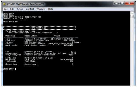
10. Once the date/time and size of the battery have been set, disconnect the computer from the BMS.
11. To ensure the board you just installed has the latest firmware, connect to the OBD-II connector and use the firmware update tools outlined in bulletin SV-ZMC-14-077.
12. Cover programming connector and push buttons with compound 70.
13. Install the power pack front cover (1) and install the 9 screws.

14. Install the center fairing panel.
15. Install the horn and bracket.
16. Install the right and left lower fairing panels.
Version 1
Battery configurations are:
• ZF7.2
• ZF14.4
• +PT - With powertank
The normal (standard) recharging time of the power pack to a 100% charge is usually*:
• ZF7.2 - 5.2 Hours
• ZF7.2 +PT - 7.5 Hours
• ZF14.4 - 9.8 Hours
• ZF14.4 +PT - 12.1 Hours
* Mild ambient temperatures.Out of the normal temperature range, charging and run-time times will vary. The power pack should not be used outside of the range of 23°F to 140°F (-5°C to 60°C); the Battery Management System (BMS) turns off the power controller outside of this range.
Power Pack Charger
Keep the power pack connected to the charger when your motorcycle is sitting in storage or if it will be sitting unused for more than 90 days. The power pack must be charged within 24 hours if fully discharged, and charged within 90 days if stored fully charged. Its recommended to plug in the motorcycle after 90 days, even if fully charged.
WARNING! Only charge the Zero power pack with the Zero charger. The charger is located under the power pack above the skid plate.
When charging the motorcycle’s power pack, the charger can be left ON, even after the power pack is fully charged.
There are two possible cases that can occur:
• When connected to the charger, the power pack will receive a full charge. Once fully charged, the charger will check the status of the power pack once every 72 hours to ensure that it maintains a full charge. When fully charged, a green light illuminates on the charger. Should the charger not read that the power pack is full, it continues to attempt to fully charge the power pack. In this event the green light may not illuminate; however, the power pack may be fully charged. To ensure that the power pack is charged, check the charge indicator on the dash display prior to riding.
• If the power pack terminates the charge before the charger reaches the state previously mentioned, then the charger continues to cycle and tops off the power pack until the power pack is removed from the charger, or the charger reaches the complete state previously noted.
The onboard charger LED indicator (1) is visible through the front of the battery housing. A circular lens displays the colored LED’s status of the charge.

When charging the motorcycle, the LEDs flash from left to right, then the LEDs display how much of the battery (on a score of 1 to 4) is charged. Next the LEDs cycle from left to right once more. For example, if 3 of the 4 LEDs are illuminated, the battery is 3/4 charged.
Charging the Power Pack
WARNING! Charge the Zero power pack with the Zero charger. It is possible for lithium ion cells to overheat and fail.
Note: Charge the Zero Power pack in a location that is well-ventilated and away from combustible materials. If charging the motorcycle outdoors, avoid charging in the rain.
The maximum power pack internal charging temperature is 131°F (55°C). If the power pack’s internal temperature is over 131°F (55°C), it will not accept a charge until it is moved to a cooler location. Also, if the power pack has just been run hard, it may internally be above 131°F (55°C) even if the ambient temperature is lower. If you experience a power pack that will not take a charge, you should ensure the internal temperature is below 131°F (55°C). If the power pack was recently run and it will not take a charge, the power pack should cool and begin taking a charge in around 30 minutes or less. The maximum charging temperature cutoff is a power pack longevity feature. Charging at higher temperatures can shorten the life of the power pack.
Note: Frequent top off charging is good for the power pack’s life span, so do not hesitate to charge frequently.
Quick Charging (Off Board Accessory Charger)
The “scalable” quick charging feature allows up to three supplemental accessory chargers (in addition to the existing integrated charger) to be connected to the motorcycle. Use of supplemental accessory chargers can reduce the charging time by up to 70%.
Note: The time for charging the motorcycle using quick charging will vary with the number of chargers used.
The accessory charging connector (1) is located above the motor. For more information on how to connect additional chargers, refer to the quick charger’s owner’s manual.

Cold and Hot Weather Considerations
Cold Weather Operation
Cold Weather operation of the motorcycle has no permanent impact on its battery pack/cells; however, the rider may see a reduction in range due to the effect cold temperature has on the amount of energy the pack/cells can release. The colder the weather, the greater the effect; so that, as compared to operation in 80°F (27°C) ambient, at 30°F (-1°C) ambient the rider could experience a temporary reduction in range of up to 30%. In extreme cold weather the motorcycle may also experience a temporary reduction in power and, correspondingly, achieved top speed. It is not recommended that the motorcycle be ridden while its battery temperature is below 23°F (-5°C). If it is, its battery needs to be put on the charger at a temperature above 32°F (0°C) as soon as the ride is concluded. It is worth noting that the Battery Management System (BMS) will not allow the battery to be discharged below -22°F (-30°C), which is the absolute lowest discharge temperature prescribed by the cell manufacturer.
Storage of the motorcycle for the winter in a non-heated garage is acceptable, as long as:
1. the coldest temperature in the garage does not fall below -31°F (-35°C)
2. the battery is left on the charger continuously
3. the battery is initially topped off at a temperature above 32°F (0°C)
Storage temperatures below -31°F (-35°C) may result in accelerated permanent decay of the battery performance, and hence it is not recommended. Above this temperature, working as a system with the BMS, the charger will ensure the battery survives winter storage with no permanent damage, even if the temperatures dip well below freezing for weeks at a time. Note that, to prevent battery damage, the BMS will prevent the charger from charging the battery at a temperature below 32°F(0°C). Again, as long as the battery was initially topped off by the charger above 32°F (0°C) and remains on the charger through the winter at temperatures above -31°F (-35°C), the system will guard the battery from damage.
Hot Weather Operation
Operation of the motorcycle in hot temperatures should not result in any noticeable performance changes. However, the BMS will not allow motorcycle operation and its associated battery discharge above 140°F (60°C), as measured at the battery. In hot temperatures greater than 110°F (43°C), the charger reduces its charge current to the battery, increasing charge time accordingly; the hotter the ambient temperature, the greater the effect. Above a battery temperature of 131°F (55°C), the BMS will no longer allow charging.
Note: Storing the motorcycle or its battery in direct sunlight in ambient temperatures above 105°F (41°C) may result in accelerated permanent decay of battery performance, and hence it is not recommended.
Battery Management System (BMS)
Every power pack contains a Battery Management System (BMS) which monitors the condition of the cells, and optimizes the charging process to provide the highest-performance, longest-range, and longest life for the power pack. The BMS safeguards the power pack by means of safety interlocks. These interlocks turn off or control certain operations that could damage the power pack. The BMS also monitors the power pack for a host of predefined conditions, and then takes actions according to those conditions. The BMS is sealed inside the power pack.
Safety Interlocks
If the BMS detects a serious internal fault, it can take either or both of two actions to prevent damage to the power pack:
• Throttle Disable. The BMS disables the throttle if the power pack is empty, or if the BMS detects certain serious internal problems. The motorcycle can’t be riden until the problem is resolved.
• Charger Disable. The BMS prevents charging if it detects certain serious internal problems - even if the power pack is connected to a charger and plugged in to AC power. The power pack cannot be charged until the problem is resolved.
Throttle Disable Interlock
The BMS communicates with the main motorcycle control module. The BMS can send a signal to the main motorcycle controller requesting that the throttle control on the motorcycle be disabled. When the throttle control is disabled, the motor will not deliver power to the rear wheel, and the motorcycle cannot be ridden. If the throttle is disabled while riding, the motorcycle will cease to provide power, and the operator must pull over to a safe location. All conditions which would cause the BMS to disable the throttle are also signaled by a flash code pattern at self-test. If you suspect that the BMS has disabled the throttle control on your motorcycle, turn the key switch OFF and back ON again to enter self-test mode. The flash code pattern from the BMS reports any of the error conditions which would cause the BMS to disable the throttle.
• Power Pack Empty
• Too Hot
• Power Pack Unbalanced
Charger-Disable Interlock
When the charger is attached and plugged in to AC power, the BMS communicates with the charger. The BMS can send a signal to the charger requesting that charging terminates immediately. When the charger is disabled, the indicator lights on the charger displays that charging has stopped. There are two conditions that cause the BMS to disable charging:
1. Too hot: The BMS detects an internal power pack temperature above 131°F (55°C).
2. Too cold: The BMS detects an internal power pack temperature below 32°F (0°C).
Version 1
|
Application
|
Specification
|
|
|
Metric
|
English
|
|
| Front Tank Bolts | 4 N•m | 35 lb in |
| Headlight Bolts | 11 N•m | 8 lb ft |
| Lower Headlight Screws | 5 N•m | 48 lb in |
| Rear Tank Bolts |
5 N•m
|
48 lb in
|
| Seat Bolts |
22 N•m
|
16 lb ft
|
Version 1
|
Part
|
Number
|
|
Headlight Bulb
|
H4 (55/60 watt)
|
|
Turn Signal Light Bulb (amber)
|
RY10W (10 watt)
|
|
Brake/Tail Light Bulb
|
LED (replace the entire unit)
|
|
Front Running Light Bulb
|
W3W (3 watt)
|
Version 1
Caution: Halogen bulbs contain gas under pressure. Handling a bulb improperly could cause it to shatter into flying glass fragments. To help avoid personal injury:
• Turn off the key switch and allow the bulb to cool before changing the bulb.
• Leave the key switch OFF until the bulb change is complete.
• Always wear eye protection when changing a halogen bulb.
• Avoid touching the glass.
Note: Use a H4 (55/60 watt) bulb for this replacement.
Removal Procedure
1. Working from behind the headlight, disconnect the headlight bulb connector (1) and remove the rubber cover (2).

2. Remove the headlight bulb retainer (1) by turning it counter-clockwise.
3. Remove the headlight bulb by pulling it straight out.

Installation Procedure
Warning: Do not touch the glass portion of the headlight bulb. Keep the headlight bulb free of contaminants. Oil from your fingers or contaminates will shorten the life of the bulb. Thoroughly clean any fingerprints or contaminates from the bulb using a clean cloth moistened with alcohol.
1. Install the headlight bulb into the lens.
2. Install the headlight bulb retainer and turn it clockwise until it locks into position.
3. Install the headlight bulb rubber cover (2).
4. Connect headlight bulb connector (1).

Version 1
Headlight Alignment
The headlight should be checked for correct alignment periodically. It must be aligned any time the suspension sag is adjusted because this will affect the headlight alignment. Before the headlight can be aligned, the suspension sag and tire pressure must be correctly adjusted. The headlight can be adjusted vertically. If the vertical adjustment is off, it will cause the beam to point too close to or too far ahead of the motorcycle. With the headlight on the low beam position, the motorcycle perpendicular to the ground, and the operator sitting on the motorcycle, verify the beam alignment. The motorcycle is shipped with the headlight at a 0.5-2.5% dip.
The adjustment screw (1) is located on the back upper right corner of the headlamp. To adjust the headlight, turn screw until the correct beam alignment is achieved.

Version 1
| Torque settings for: Turn Signal Flasher Replacement | |
| Item | Torque Setting |
| Seat Bolts | 22 N•m (16 lb ft) |
| Rear Tank Bolts | 5 N•m (48 lb in) |
| Front Tank Bolts | 4 N•m (35 lb in) |
 Show Torque Table
Required Tools
• 3mm hex wrench
• 5mm hex wrench
• Philips screwdriver
Fastener torques
• Seat bolts 22 N•m (16 lb ft)
• Rear tank bolts 5 N•m (48 lb in)
• Front tank bolts 4 N•m (35 lb in)
Important: The turn signal flasher is located at the front of the frame under the tank storage compartment.
Removal Procedure
1. Remove the seat.
2. Remove the tank assembly (S TANK ASSEMBLY BLACK, S TANK ASSEMBLY YELLOW #2, DS TANK ASSEMBLY BLACK, DS TANK ASSEMBLY WHITE, DS TANK ASSEMBLY ORANGE #2, POWER TANK ASSY< SR RED 24-08074 RED SR TANK (non power tank), MY15 PWER TANK ASSY> DS ORANGE, MY15 PWER TANK ASSY> DS WHITE, MY15 POWER TANK ASSY> S BLACK, MY15 POWER TANK ASSY> S YELLOW, MY15 POWER TANK ASSY> SR RED).
3. Disconnect the C42 turn signal flasher harness connector (1) and remove the flasher.
4. Remove and discard the zip tie, securing the flasher to the harness.
Installation Procedure
1. Connect the C42 turn signal flasher harness connector (1).
2. Install a new zip tie securing the flasher to the harness in the same location as removed.
3. Install the tank assembly.
4. Install the seat.
Version 1
Handlebar Controls

Legend
1. Flash-to-Pass
2. Headlight High/Low Beam Switch
3. Turn Signal Switch
4. Hazard Switch
Flash-to-Pass
When the headlight is in the low beam position, push the flash-to-pass switch and the high beam will illuminate and will stay illuminated until the switch is released. When released, this switch will default back to the low beam position. The instrument panel high beam indicator will also illuminate.
Headlight High/Low Beam Switch
When the switch is pushed, the headlight will change from low beam to high beam. It will stay in the selected position until it is switched back. When in high beam position, the high beam indicator on the instrument panel will illuminate.
Instrument Panel High Beam Indicator

High Beam Indicator
When the headlight is in high beam position, or the flash-to-pass switch is pressed, this indicator will illuminate.
Instrument Panel Turn Signal Indicator
Turn Signal Switch
When the turn signal switch is pushed in the left or right position, the corresponding front and rear turn signal will flash. The turn signals must always be cancelled manually on the motorcycle. Push in on the switch and it will return to the center or OFF position. When the turn signal switch is ON, the corresponding turn signal indicator on the instrument panel will illuminate.


Hazard Warning Flasher Switch
When the top of the switch is pressed, the turn signals flash to warn other drivers of situations which include needing to stop or park under emergency conditions. When the bottom of the switch is pressed, the hazard warning circuit will turn off.
Version 1
|
Application
|
Specification
|
|
|
Metric
|
English
|
|
| Brake Pedal Pivot Bolt* | 46 N•m | 34 lb ft |
| Swingarm Pivot Bolt | 102 N•m | 75 lb ft |
| Rear Axle Shaft Nut* | 102 N•m | 75 lb ft |
| Motor Shaft Sprocket Bolt* | 71 N•m | 52 lb ft |
| Shock Lower Nut and Bolt | 54 N•m | 40 lb ft |
| Rear Sprocket Bolt* | 35 N•m | 26 lb ft |
| Rear Axle Adjuster Jam Nut | 26 N•m | 19 lb ft |
* Use LOCTITE® 242® (or equivalent)
Version 1
The belt can make noise when forced to run hard against the flanges on the sprockets. This can be due to sprocket misalignment, wheel misalignment, or runout in the drive caused by damaged components. Spraying water on the belt may quiet the drive for a few minutes, but the permanent solution is to correct the alignment or replace the damaged components.
In most cases simply hosing off the belt and sprockets after a ride will end the noise. If noise continues, the solution is simple: Spray the belt with water, wait for it to dry, and apply a thin coating of dry silicone spray to the tooth side of the belt. Dry silicone dries instantly, helps shed grit, and does not affect the longevity of the belt.
1. Remove the key from the key switch.
2. Raise and safely support the motorcycle so that the rear wheel is off the ground.
3. Spray the belt with water and allow it to fully dry.
Caution: Do not allow any of the silicone spray to get on the brake rotor or brake pads.
4. Using a dry silicone lubricant and a clean shop towel, with the shop towel on the opposite side of the belt, spray a 3 to 4 inch spot on the inside of the belt.
5. Rotate the tire and spray another 3 to 4 inch spot on the belt opposite where it was sprayed before.
6. Rotate the wheel in order to evenly distribute the lubricant.
Version 1
| Torque settings for: Belt Replacement | |
| Item | Torque Setting |
| Swingarm Pivot Bolts | 102 N•m (75 lb ft) |
| Brake Pedal Pivot Bolt | 46 N•m (34 lb ft) |
| Axle Adjuster Jam Nut | 26 N•m (19 lb ft) |
 Show Torque Table
Required Tools
• 10mm hex wrench
• 3mm hex wrench
• Two 13mm wrenches
• 27mm socket and socket wrench
Fastener Torques
Notice: Refer to Fastener Notice in General Information.
• Swingarm pivot bolts 102 N•m (75 lb ft)
• Brake pedal pivot bolt* to 46 N•m (34 lb ft)
• Axle adjuster jam nut 26 N•m (19 lb ft)
*Use LOCTITE® 242® (or equivalent)
Notice: Refer to Description and Operation for proper handling of the belt.
Uncoiling the Belt
Notice: Improper uncoiling may cause permanent damage to the belt.
1. Hold the belt chest high in front of your body and hold the outer coil with both hands.

2. Move your hands away from each other slowly, until the belt uncoils on its own.

3. Now the belt is properly uncoiled.

Removal Procedure
Notice: If reusing the belt, mark the direction on the belt so it can be installed in that direction.
1. Raise and safely support the motorcycle.
Note: The location of the swingarm ground strap and brake line clips, before removing the rear fender.
2. Remove the 4 bolts securing the rear fender to the swingarm, and remove the fender.
3. Loosen the rear axle nut (1).
4. Loosen the belt tensioner jam nut (3) and adjuster bolt (2). Right side shown, left side similar.

5. Slide the wheel forward and remove the belt from the sprocket.
6. Remove the brake pedal pivot bolt.
7. Remove the protective rubber cap and pivot bolt (1). Right side shown, left side similar.

8. Pull the swingarm out enough to remove the belt (BELT DRIVE, 220T, 8MM PITCH, 14MM WIDE, NEW LOGO, BELT 158T 11MM PITCH 17MM WIDE) from the motor pulley.
Installation Procedure
1. Inspect the sprockets for wear or damage, replace as needed.
2. Pull back on the swingarm enough to install on the motor pulley.
Notice: Refer to Fastener Notice in General Information.
3. Install the swingarm pivot bolts (1) and tighten. Right side shown, left side similar.
Tighten
Swingarm pivot bolts to 102 N•m (75 lb ft)

4. Install the protective rubber caps.
5. Install the brake pedal pivot bolt.
Tighten
Brake pedal pivot bolt to 46 N•m (34 lb ft)
6. Install the belt on the wheel sprocket.
7. Adjust the belt tension. Refer to Belt Tension Adjustment.
8. Install the fender, ground strap and brake line clips onto the swingarm.
9. Lower the motorcycle.
Version 1
| Torque settings for: Using Gates® Carbon Drive™ Smartphone Application | |
| Item | Torque Setting |
| Axle Shaft Nut | 102 N•m (75 lb ft) |
| Axle Adjuster Jam Nut | 26 N•m (19 lb ft) |
 Show Torque Table
Required Tools
• Smart Phone with Gates Carbon Drive Application Installed
• 3mm hex wrench
• 27mm socket and socket wrench
• 13mm wrench
Fastener Torques
Notice: Refer to Fastener Notice in General Information.
• Axle shaft nut* to 102 N•m (75 lb ft)
• Axle adjuster jam nut 26 N•m (16 lb ft)
*Use LOCTITE® 242® (or equivalent)
Checking Procedure
|
Belt Pitch
|
Recommended Tension Range
|
|
11 mm
|
42.5 Hz - 73.6 Hz
|
The drive belt tension can be checked by using the Gates® Carbon Drive™ Smartphone application, which measures belt tension frequency. The application is available for free to download at both the Apple iTunes® store and Google Play® store. iTunes® is a registered trademark of Apple. Google Play® store is a registered trademark of Google. Note: Perform belt frequency measurement on the lower belt span, close to the center (between the sprockets). Note: The application works best in a quiet environment. Note: The following application instructions may differ between phones.

1. Remove the key from the key switch.
Note: The location of the swingarm ground strap and brake line clips, before removing the rear fender.
2. Remove the 4 bolts securing the rear fender to the swingarm, and remove the fender.
3. From the application, click the Tension icon and measure.
4. Confirm the phone’s microphone is ON (if applicable).
5. Hold the phone, so the microphone is as close to the drive belt as possible (without touching the belt).
6. Pluck the belt with your thumb or a wrench (as shown) so that it vibrates like a guitar string.

7. The microphone will measure vibration’s frequency.
8. Rotate the rear wheel a quarter-turn and repeat the frequency measurement.
9. Compare your belt’s frequency readings to the recommended range values (see chart above).
10. If the tension is not within specification, the belt will need to be adjusted. Refer to the adjustment procedure below.
Adjustment Procedure
1. Remove the 4 bolts securing the rear fender to the swingarm, and remove the fender.
2. Loosen the rear axle shaft nut (1).
3. Loosen the jam nuts (3). Adjust the belt tension by turning the axle adjusters (2) an equal number of turns to keep the wheel aligned until the specification is achieved.
4. Tighten the jam nuts.
Tighten
Axle adjuster jam nut to 26 N•m (19 lb ft)

Notice: Refer to Fastener Notice in General Information.
5. Tighten the axle shaft nut.
Tighten
Axle shaft nut to 102 N•m (75 lb ft)
6. Road test the motorcycle. Refer to Road Testing Procedure.
7. Recheck the belt for proper tension adjustment after the test ride and readjust if necessary.
8. Install the fender
Version 1
| Torque settings for: Using Tension Tester Tool | |
| Item | Torque Setting |
| Axle Shaft Nut | 102 N•m (75 lb ft) |
| Axle Adjuster Jam Nut | 26 N•m (19 lb ft) |
 Show Torque Table
Required Tools
• Belt Tension Tester
• 3mm hex wrench
• 27mm socket and socket wrench
• 13mm wrench
Fastener Torques
Notice: Refer to Fastener Notice in General Information.
• Axle shaft nut* to 102 N•m (75 lb ft)
• Axle adjuster jam nut 26 N•m (19 lb ft)
*Use LOCTITE® 242® (or equivalent)
Checking Procedure
|
Belt Pitch
|
Recommended Tension Range
|
|
11 mm
|
25 kg to 76.5 kg
|
The Tension Tester has a plastic measurement arm, located in a slot. Along this slot there is a measuring scale. The point of intersection of the measurement arm and the measuring scale shows the tension of the belt. There is a button (clicking pad) on the upper side of the Tension Tester where you can secure your finger with a rubber band holder. A spring is located underneath this clicking pad. If a certain pressure is applied to the spring, it makes a clicking sound.

1. Remove the key from the key switch.
Note: The location of the swingarm ground strap and brake line clips, before removing the rear fender.
2. Remove the 4 bolts securing the rear fender to the swingarm, and remove the fender.
3. Press the Tension Tester steadily to the middle of the upper side of the belt. The “lip” will lead the tester to the belt.
4. Slowly increase the pressure on the tester, until you hear a clicking sound. Do not increase the pressure after the tester has clicked.
5. Remove the tester carefully from the belt. Avoid rough movements of the tester as this would change the results of the measurement.
6. If the tension is not within specification (see chart above), the belt will need to be adjusted. Refer to the adjustment procedure below.
Adjustment Procedure
1. Remove the 4 bolts securing the rear fender to the swingarm, and remove the fender.
2. Loosen the rear axle shaft nut (1).
3. Loosen the jam nuts (3). Adjust the belt tension by turning the axle adjusters (2) an equal number of turns to keep the wheel aligned until the specification is achieved.
Notice: Refer to Fastener Notice in General Information.
4. Tighten the jam nuts.
Tighten
Axle adjuster jam nut to 26 N•m (19 lb ft)

5. Tighten the axle shaft nut.
Tighten
Axle shaft nut to 102 N•m (75 lb ft)
6. Road test the motorcycle. Refer to Road Testing Procedure.
7. Recheck the belt for proper tension adjustment after the test ride and readjust if necessary.
8. Install the fender , ground strap and brake line clips onto the swingarm.
Version 1
| Torque settings for: Motor Sprocket Replacement | |
| Item | Torque Setting |
| Motor Shaft Sprocket Bolt | 71 N•m (52 lb ft) |
 Show Torque Table
Required Tools
• 6mm hex wrench
• Gear puller
Fastener Torques
Notice: Refer to Fastener Notice in General Information.
• Motor shaft sprocket bolt* to 71 N•m (52 lb ft)
*Use LOCTITE® 242® (or equivalent)
Removal Procedure
Note: If reusing the belt (BELT 158T 11MM PITCH 17MM WIDE, BELT DRIVE, 220T, 8MM PITCH, 14MM WIDE, NEW LOGO), mark the direction on the belt so it can be installed in that direction.
1. Remove the motor.(ZF75-7 IPM 28T MOTOR KIT, ZF75-5 S IPM MOTOR SPLINED SHAFT). Refer to Motor Replacement.
2. Remove the motor shaft bolt and washer.
3. Using a gear puller remove the pulley (SPROCKET FRONT, BELT DRIVE 28T, 8MM PITCH, 15MM WIDE 1" BORE, MOTOR SPROCKET 20T 11MM PITCH 17MM WIDE BELT ASSEMBLED) from the motor shaft. Use the threaded holes in the pulley for the gear puller, DO NOT use the outside edge of the pulley for removal. Follow the manufactures instructions for the gear puller you are using.
4. Ensure that the shaft spacer remains in place if used.
5. Clean all fastener threads of LOCTITE®, oil, or grease.
Installation Procedure
1. Ensure that the shaft spacer is in place if used.
2. Apply Green LOCTITE® 680® to the motor shaft.
3. Apply LOCTITE® 242® to the threaded portion of the motor shaft bolt.
Notice: Refer to Fastener Notice in General Information.
4. Install the motor shaft sprocket bolt and washer. Ensure that the washer's center hole groove is facing away from the motor.
Tighten
The motor shaft sprocket bolt to 71 N•m (52 lb ft).
5. Install the motor. Refer to Motor Replacement.
Version 1
| Torque settings for: Rear Drive Sprocket Replacement | |
| Item | Torque Setting |
| Rear Sprocket Bolts | 35 N•m (26 lb ft) |
| Axle Shaft Nut | 102 N•m (75 lb ft) |
 Show Torque Table
Required Tools
• 27mm socket and socket wrench
• 5mm hex wrench
Fastener Torques
Notice: Refer to Fastener Notice in General Information.
• Rear sprocket bolts* to 35 N•m (26 lb ft)
• Axle shaft nut* to 102 N•m (75 lb ft)
*Use LOCTITE® 242® (or equivalent)
Removal Procedure
1. Securely raise and support the motorcycle so that the rear wheel is off the ground.
2. Remove the rear axle nut (1) and tap out the axle shaft. Note: Be aware of the axle shaft spacer on the left of the wheel.

3. Lower the wheel and remove the drive belt from the sprocket.
Important: Support the brake caliper with mechanic wire, or equivalent, whenever it is separated from its mount and the hydraulic flexible brake hose is still connected. Failure to support the caliper in this manner will cause the flexible brake hose to bear the weight of the caliper, which may cause damage to the brake hose and in turn may cause a brake fluid leak.
4. Move and support the brake caliper with mechanic's wire or equivalent. DO NOT disconnect the hydraulic brake hose from the brake caliper.
5. Remove the 4 Allen bolts (1) and nuts securing the sprocket to the wheel.
6. Remove the rear sprocket (2) from the wheel.

Installation Procedure
Important: Whenever the sprocket has been separated from the wheel flange, any rust or contaminants must be cleaned from the wheel flange and the sprocket mating surfaces. Failure to do this may result in excessive assembled lateral runout (LRO) of the sprocket, which could lead to vibration.
1. Inspect the sprocket and wheel flange surface for rust or contamination. Remove rust or contamination if necessary.
2. Install the sprocket (2) onto the wheel flange.
Notice: Refer to Fastener Notice in General Information.
3. Install the sprocket bolts (1) and nuts. Tighten in a crisscross pattern.
Tighten
The rear sprocket bolts to 35 N•m (26 lb ft)

4. Place the caliper into position on the swingarm.
5. Place the drive belt onto the wheel sprocket, ensuring that the left wheel spacer and the ABS sensor are in place.
6. Move the wheel into position. Ensure that the brake rotor is centered between the brake pads.
7. Verify belt tension. Refer to Belt Tension Adjustment.
8. Slide the axle shaft (2) through the swingarm and wheel and install the nut (1).
Tighten
Axle shaft nut to 102 N•m (75 lb ft)

Version 1
Clean the belt with mild soap and water when washing the motorcycle. Towel dry and inspect for the following:
• Cuts or unusual wear patterns.
• Damage to the center of the belt.
• Outside edge beveling. Some beveling is common but it indicates that sprockets are misaligned.
• Outside ribbed surface for signs of stone puncture.
• Inside (tooth portion) of belt for exposed tensile cords normally covered by nylon layer and polyethylene layer. This condition will result in belt failure and indicates worn sprocket teeth.
• Signs of puncture or cracking at the base of the belt teeth.
If any of the above conditions are found, the belt should be replaced.
Version 1
Drive Belt
Proper belt tension is essential for optimum operation of the Gates Carbon Drive System. Lack of belt tension can lead to so-called “ratcheting," which is where the teeth of the belt will slide over the teeth of the rear sprocket. This causes not only an unpleasant sound, it also can cause damage to the carbon tensile cords, which would render a belt useless. If ratcheting has occurred, you should replace the belt before the next time it is to be used. Too much tension can also cause damage to the bearings within the rear hub, and can increase the wear of your drive system, causing the system to drag.
The belt should be replaced at 37,000 km (24,000 miles) S/SR/DS and 25,000 km (16,000 miles) DSR.
For cleaning, use only water and a soft brush. Do not use any type of detergent.
Proper handling of the belt is crucial to obtain maximum life expectancy. Bending or twisting of the belt may cause damage to the carbon fibers inside the belt. Avoid the following conditions when handling the belt.

Legend
1. Crimping
2. Twisting
3. Back Bending
4. Inverting
5. Zip Tying
6. Using as a wrench
Version 1
|
Application
|
Specification
|
|
|
Metric
|
English
|
|
|
Rear Axle Shaft Nut*
|
102 N•m
|
75 lb ft
|
|
Rear Shock Bolts
|
54 N•m
|
40 lb ft
|
|
Swingarm Pivot Bolts
|
102 N•m
|
75 lb ft
|
|
Brake Pedal Pivot Bolt*
|
46 N•m
|
34 lb ft
|
|
Steering Stem Nut
|
102 N•m
|
75 lb ft
|
|
Triple Clamp Upper Pinch Bolt*
|
20 N•m
|
15 lb ft
|
|
Triple Clamp Lower Pinch Bolt*
|
23 N•m
|
17 lb ft
|
|
Front Axle Shaft Bolts
|
54 N•m
|
40 lb ft
|
|
Front Axle Shaft Pinch Bolts
|
12 N•m
|
9 lb ft
|
|
Handlebar Clamp Bolts
|
26 N•m
|
19 lb ft
|
|
Front Brake Caliper Bolts
|
26 N•m
|
19 lb ft
|
|
Steering Stem Lock Nut
|
34 N•m
|
25 lb ft
|
|
Lower headlamp bracket bolts
|
5 N•m
|
48 lb in
|
* Use LOCTITE® 242® (or equivalent)
Version 1
ZF7.2
| Model |
S |
SP |
DS |
DSP |
||||||||
| Component |
Fork |
Fork |
Fork |
Fork |
||||||||
| Side |
Left |
Right |
Left |
Right |
Left |
Right |
Left |
Right | ||||
| Part # | 22-05874-02 | 22-05875-02 | 22-05874-02 | 22-05875-02 | 22-05877-02 | 22-05878-02 | 22-05877-02 | 22-05878-02 | ||||
| Free Length | 721±2.0mm | 721±2.0mm | 769.4±2.0mm | 769.4±2.0mm | ||||||||
| Max Length | 727mm | 727mm | 778mm | 778mm | ||||||||
| Min Length | 568mm | 568mm | 600mm | 600mm | ||||||||
| Stroke | 159mm | 159mm | 178mm | 178mm | ||||||||
| Spring Rate | 7.4 N/mm | 7.4 N/mm | 6.0-7.0 N/mm** | 6.0-7.0 N/mm** | ||||||||
| Oil | SS No.8 | SS No.8 | SS No.8 | SS No.8 | ||||||||
| Oil Volume | 371±2.5cm3 | 371±2.5cm3 | 408±2.5cm3 | 408±2.5cm3 | ||||||||
| Oil Level | 178mm* | 178mm* | 170mm* | 170mm* | ||||||||
| Rebound (Tension) | Max - 9 clicks | Max - 9 clicks | Max - 12 clicks | Max - 12 clicks | ||||||||
| Compression | Max - 8 clicks | Max - 8 clicks | Max - 7 clicks | Max - 7 clicks | ||||||||
| Preload | Min + 7.5 turns | Min + 7.5 turns | Min + 5.5 turns | Min + 5.5 turns | ||||||||
| Outer Tube Finish | Natural Anodized (silver) | Natural Anodized (silver) | Natural Anodized (silver) | Natural Anodized (silver) | ||||||||
| Slide Tube Finish | Nickel - Hard Chrome | Nickel - Hard Chrome | Nickel - Hard Chrome | Nickel - Hard Chrome | ||||||||
| Rebound (Tension) Finish | Red Anodized | Red Anodized | Blue Anodized | Blue Anodized | ||||||||
| Compression Finish | Red Anodized | Red Anodized | Blue Anodized | Blue Anodized | ||||||||
ZF14.4
| Model |
S |
SP |
SR |
DS |
DSP |
DSR |
||||||||||||
| Component |
Fork |
Fork |
Fork |
Fork |
Fork |
Fork |
||||||||||||
| Side |
Left |
Right |
Left |
Right |
Left |
Right |
Left |
Right |
Left |
Right |
Left |
Right |
||||||
| Part # | 22-05874-02 | 22-05875-02 | 22-05874-02 | 22-05875-02 | 22-05874-02 | 22-05875-02 | 22-05877-02 | 22-05878-02 | 22-05877-02 | 22-05878-02 | 22-05877-02 | 22-05878-02 | ||||||
| Free Length | 721±2.0mm | 721±2.0mm | 721±2.0mm | 769.4±2.0mm | 769.4±2.0mm | 769.4±2.0mm | ||||||||||||
| Max Length | 727mm | 727mm | 727mm | 778mm | 778mm | 778mm | ||||||||||||
| Min Length | 568mm | 568mm | 568mm | 600mm | 600mm | 600mm | ||||||||||||
| Stroke | 159mm | 159mm | 159mm | 178mm | 178mm | 178mm | ||||||||||||
| Spring Rate | 7.4 N/mm | 7.4 N/mm | 7.4 N/mm | 6.0-7.0 N/mm** | 6.0-7.0 N/mm** | 6.0-7.0 N/mm** | ||||||||||||
| Oil | SS No.8 | SS No.8 | SS No.8 | SS No.8 | SS No.8 | SS No.8 | ||||||||||||
| Oil Volume | 443±2.5cm3 | 443±2.5cm3 | 443±2.5cm3 | 408±2.5cm3 | 408±2.5cm3 | 408±2.5cm3 | ||||||||||||
| Oil Level | 112mm* | 112mm* | 112mm* | 170mm* | 170mm* | 170mm* | ||||||||||||
| Rebound (Tension) | Max - 9 clicks | Max - 9 clicks | Max - 9 clicks | Max - 11 clicks | Max - 11 clicks | Max - 11 clicks | ||||||||||||
| Compression | Max - 6 clicks | Max - 6 clicks | Max - 6 clicks | Max - 6 clicks | Max - 6 clicks | Max - 6 clicks | ||||||||||||
| Preload | Min + 7.5 turns | Min + 7.5 turns | Min + 7.5 turns | Min + 7.5 turns | Min + 7.5 turns | Min + 7.5 turns | ||||||||||||
| Outer Tube Finish | Natural Anodized (silver) | Natural Anodized (silver) | Natural Anodized (silver) | Natural Anodized (silver) | Natural Anodized (silver) | Natural Anodized (silver) | ||||||||||||
| Slide Tube Finish | Nickel - Hard Chrome | Nickel - Hard Chrome | Nickel - Hard Chrome | Nickel - Hard Chrome | Nickel - Hard Chrome | Nickel - Hard Chrome | ||||||||||||
| Rebound (Tension) Finish | Red Anodized | Red Anodized | Red Anodized | Blue Anodized | Blue Anodized | Blue Anodized | ||||||||||||
| Compression Finish | Red Anodized | Red Anodized | Red Anodized | Blue Anodized | Blue Anodized | Blue Anodized | ||||||||||||
*Measured from outer tube end to oil surface (condition: spring, spring joint, spring collar, seat rubber, slider, fork bolt are removed and dust seal touches axle holder)
**Dual Rate
Version 1
Factory Supplied Rear Shock Settings
ZF7.2
| Model |
S |
SP |
DS |
||||||
| Component |
Shock |
Shock |
Shock |
||||||
| Part # | 22-05881-02 | 22-05881-02 | 22-05882-03 | ||||||
| Free Length | 278.5±2.0mm | 278.5±2.0mm | 284.5±2.0mm | ||||||
| Max Length | 279mm | 279mm | 285mm | ||||||
| Min Length | 219mm | 219mm | 219mm | ||||||
| Stroke | 60mm | 60mm | 66mm | ||||||
| Spring Rate | 98.1 N/mm | 98.1 N/mm | 96.1 N/mm | ||||||
| Rebound (Tension) | Max - 8 clicks | Max - 8 clicks | Max - 12 clicks | ||||||
| Compression | Max - 14 clicks | Max - 14 clicks | Max - 10 clicks | ||||||
| Preload | 5th Position | 5th Position | 5th Position | ||||||
| Body Finish | Natural Anodized (silver) | Natural Anodized (silver) | Natural Anodized (silver) | ||||||
| Rod Finish | Nickel - Hard Chrome | Nickel - Hard Chrome | Nickel - Hard Chrome | ||||||
| Rebound (Tension) Finish | Red Anodized | Red Anodized | Blue Anodized | ||||||
| Compression Finish | Red Anodized | Red Anodized | Blue Anodized | ||||||
ZF14.4
| Model |
S |
SP |
SR |
DS |
DSP |
DSR |
||||||||||||
| Component |
Shock |
Shock |
Shock |
Shock |
Shock |
Shock |
||||||||||||
| Part # | 22-05881-02 | 22-05881-02 | 22-05881-02 | 22-05882-03 | 22-05882-03 | 22-05882-03 | ||||||||||||
| Free Length | 278.5±2.0mm | 278.5±2.0mm | 278.5±2.0mm | 284.5±2.0mm | 284.5±2.0mm | 284.5±2.0mm | ||||||||||||
| Max Length | 279mm | 279mm | 279mm | 285mm | 285mm | 285mm | ||||||||||||
| Min Length | 219mm | 219mm | 219mm | 219mm | 219mm | 219mm | ||||||||||||
| Stroke | 60mm | 60mm | 60mm | 66mm | 66mm | 66mm | ||||||||||||
| Spring Rate | 98.1 N/mm | 98.1 N/mm | 98.1 N/mm | 96.1 N/mm | 96.1 N/mm | 96.1 N/mm | ||||||||||||
| Rebound (Tension) | Max - 6 clicks | Max - 6 clicks | Max - 6 clicks | Max - 9 clicks | Max - 9 clicks | Max - 9 clicks | ||||||||||||
| Compression | Max - 12 clicks | Max - 12 clicks | Max - 12 clicks | Max - 13 clicks | Max - 13 clicks | Max - 13 clicks | ||||||||||||
| Preload | 5th Position | 5th Position | 5th Position | 5th Position | 5th Position | 5th Position | ||||||||||||
| Body Finish | Natural Anodized (silver) | Natural Anodized (silver) | Natural Anodized (silver) | Natural Anodized (silver) | Natural Anodized (silver) | Natural Anodized (silver) | ||||||||||||
| Rod Finish | Nickel - Hard Chrome | Nickel - Hard Chrome | Nickel - Hard Chrome | Nickel - Hard Chrome | Nickel - Hard Chrome | Nickel - Hard Chrome | ||||||||||||
| Rebound (Tension) Finish | Red Anodized | Red Anodized | Red Anodized | Blue Anodized | Blue Anodized | Blue Anodized | ||||||||||||
| Compression Finish | Red Anodized | Red Anodized | Red Anodized | Blue Anodized | Blue Anodized | Blue Anodized | ||||||||||||
*Measured from outer tube end to oil surface (condition: spring, spring joint, spring collar, seat rubber, slider, fork bolt are removed and dust seal touches axle holder)
**Dual Rate
Preferred Rear Sag Settings
|
MODEL
|
SAG
|
|
S and SR
|
45 mm (1.77 in)
|
|
DS and DSR
|
59 mm (2.32 in)
|
Version 1
Preliminary Checks
Since problems in steering, suspension, tires, and wheels involve several systems, all systems must be considered when diagnosing a complaint. In order to avoid pursuing the wrong symptom, always road test the vehicle first. Refer to Road Testing Procedure. Proceed with the following preliminary checks and correct any substandard condition that is found.
• Inspect the tires for the following:
- Pressure
- Wear
- Size
- Brand
- Construction
- Balance
- Runout
• Inspect the wheels for the following:
- Size
- Balance
- Runout
- Damage
- Proper installation
• Inspect the following for loose connections, wear, or damage:
- The steering fork
- The front suspension
- The rear suspension
Version 1
Compression Damping
Compression controls the initial "bump travel" of the suspension. As the wheel is forced upward by the bump, the compression circuit controls the speed at which the suspension compresses, helping to keep the spring from allowing an excessive amount of travel or bottoming of the suspension.
Damping is viscous friction caused by forcing a fluid through some type of restriction. Damping force is determined by the speed of the fluid movement, not the distance of suspension travel.
Rebound Damping
Controls the extension of the fork or shock after it compresses over a bump.Ride Height
Raising or lowering the fork or lengthening or shortening the shock to change the chassis height of the motorcycle.Spring Rate
Force needed compress the spring a given distanceFork
|
Adjustment
|
Setting
|
Effect
|
|
Compression Damping
|
Too much
|
Bike difficult to turn in and will steer wide through the turn
Front wheel skips on bumps Forks judder when braking in a straight Front end feels harsh on small bumps |
|
Not enough
|
Forks dive too quickly, possibly bottoming out
Rear end wants to come around during hard braking Front end has a mushy and semi-vague feeling, similar to lack of rebound damping |
|
|
Rebound Damping
|
Too much
|
Front end chatters coming out of corners
Forks pack down on fast bumpy pavement Front end wiggles or tank-slaps on hard acceleration out of bumpy corners Harsh ride due to forks packing down |
|
Not enough
|
Excessive pogo action through chicanes
Front end shakes (not chatters) in corners Front end shoots up too fast after braking Feels plush when riding straight, but mushy in corners and traction feel is poor When flicking into a corner at speed, the bike will porpoise or wallow a bit before settling down |
|
|
Ride Height
|
Too low
|
Lack of high speed stability
Easy turn-in into corners |
|
Too high
|
Sluggish or high effort turn-in into corners
|
|
|
Spring Rate
|
Too soft
|
Forks compress too much on smooth turns
Forks bottom out during hard braking or large bumps Creates oversteer Can cause front to tuck under Turns easily into corners |
|
Too stiff
|
Creates understeer
Lose front end on corner entry Harsh in corners Front end chatters coming out of corners Bike difficult to turn in Feels good under braking Front wheel skips on bumps |
Rear Shock
|
Compression Damping
|
Too much
|
Shock rigid and harsh, but not as bad as too much rebound damping
Rear wheel skips when braking on rippled pavement Very little rear end squat on acceleration |
|
Not enough
|
Shock bottoms out on medium sized bumps
Rear end squats on acceleration Possible bottoming of shock Bike steers wide exiting corners (rear-low, nose-high) |
|
|
Rebound Damping
|
Too much
|
Rear wheel hops on turns with small bumps, especially washboard
Rear wheel skips when braking on rippled pavement Rear end packs down over series of bumps Rear feels harsh Bike steers wide exiting corners (rear-low, nose-high) |
|
Not enough
|
Too much kicking up when braking hard
Bike wallows when exiting corners or in long rolling dips in sweepers Rear wheel chatters under hard acceleration over bumps Too much chassis pitch/pogo stick action |
|
|
Ride Height
|
Too low
|
Motorcycle understeers on exit corners
Difficult to change direction Poor grip from front tire on exit corners |
|
Too high
|
Lack of high speed stability
Poor grip from rear tire Unstable under heavy braking |
|
|
Spring Rate
|
Too soft
|
Ride is soft
Rear end squats on acceleration "Light" feeling on the front |
|
Too stiff
|
Easy turn-in to corners
Ride is harsh Poor rear wheel traction |
Version 1
| Torque settings for: Steering Head Service | |
| Item | Torque Setting |
| Steering Stem Lock Nut | 34 N•m (25 lb ft) |
| Lower Triple Clamp Pinch Bolts | 23 N•m (17 lb ft) |
| Steering Stem Nut | 81 N•m (60 lb ft) |
| Upper Triple Clamp Pinch Bolts | 20 N•m (15 lb ft) |
| Handlebar Clamp Bolts | 26 N•m (19 lb ft) |
| Front Axle Shaft | 54 N•m (40 lb ft) |
| Front Axle Shaft Pinch Bolts | 12 N•m (9 lb ft) |
| Front Brake Caliper Bolts | 26 N•m (19 lb ft) |
| Lower Headlamp Bracket Bolts | 5 N•m (48 lb in) |
 Show Torque Table
Required Tools
• 17mm wrench
• Steering stem lock nut socket
• 16mm hex wrench
• 41mm socket
• 6mm hex wrench
• 5mm hex wrench
• 3mm hex wrench
Replacement Parts
• Dust seals
• Lower Triple Clamp Assembly – S/DS/SR/DSR
Fastener Torques
Notice: Refer to Fastener Notice in General Information.
• Steering stem lock nut to 34 N•m (25 lb ft)
• Lower triple clamp pinch bolts* to 23 N•m (15 lb ft)
• Steering stem nut to 81 N•m (60 lb ft)
• Upper triple clamp pinch bolts* to 20 N•m (15 lb ft)
• Handlebar clamp bolts to 26 N•m (19 lb ft)
• Front axle shaft** to 54 N•m (40 lb ft)
• Front axle shaft pinch bolts* 12 N•m (9 lb ft)
• Front brake caliper bolts to 26 N•m (19 lb ft)
• Lower headlamp bracket bolts to 5 N•m (48 lb in)
*Use LOCTITE® 242® (or equivalent)
**Use Anti-Seize (or equivalent)
Exploded View

Legend:
1. Steering Stem Nut
2. Washer
3. Upper Triple Clamp
4. Steering Stem Lock Nut
5. Dust Seal
6. Bearing and Inner Race
7. Bearing
8. Dust Seal
9. Lower Triple Clamp
Removal Procedure
1. Remove the key from the key switch and support the motorcycle upright on a stand with the front wheel off the ground.
2. Remove the 2 caliper bolts (1). Support the brake caliper (2) with mechanic's wire, or equivalent, whenever it is separated from its mount and the hydraulic flexible brake hose is still connected. Failure to support the caliper in this manner will cause the flexible brake hose to bear the weight of the caliper, which may cause damage to the brake hose and in turn may cause a brake fluid leak.

3. Slide the brake caliper off of the brake rotor and support the brake caliper with mechanic's wire or equivalent. DO NOT disconnect the hydraulic brake hose from the brake caliper.
4. Remove the front axle shaft pinch bolts (2) from the right lower fork leg.
5. Unscrew the front axle (1) then slide the axle out of the fork.

6. Remove sensor wire/brake line clamp from fork guard.
7. Remove the front fender (PAINTED S/SR FRONT FENDER YELLOW #3, PAINTED S/SR FRONT FENDER WHITE #3, PAINTED S/SR FRONT FENDER BLACK #3, PAINTED S/SR FRONT FENDER RED #3, FRONT FENDER DIRT BRAKE LINE HOLE).
8. Remove the lower headlight bolts (1) from both sides.
9. Remove the lower headlight bracket bolts (2) from both sides and the bracket (3).
10. Loosen the lower triple clamp pinch bolts (4) from both sides.

11. Remove the left upper headlight bracket bolts (1) and then remove the right headlight bracket bolts.

12. Hang the headlight and instrument panel assembly forward of the motorcycle and cover them to protect from damage.
13. Remove handlebar bolts (1), clamps, and the handlebar. Lay forward on headlight and instrument panel assembly.
14. Loosen the upper triple clamp pinch bolts (2).
15. Remove steering stem nut and washer (3).

16. Remove upper triple clamp. Place towel between triple clamp and handlebar for protection.
17. Remove both of the forks (S FORK 41MM LEFT, S FORK 41MM RIGHT, DS FORK 41MM LEFT, DS FORK 41MM RIGHT) from lower triple clamp.
18. Using a steering stem nut socket (1) remove steering stem lock nut.

19. Remove lower triple clamp assembly from frame.
20. Remove all bearings and dust seals.

Inspection Procedure
1. Clean head tube bore completely.
2. Clean bearing races and steering stem with brake cleaner or alcohol.
3. Inspect steering stem just above the lower inner race for scoring/gouging of steering stem.
If you find scoring or damage to steering stem, you must replace the lower triple clamp assembly, bearings, and races. If the bearing races are loose in the head tube bores, the frame must be replaced.
If scoring/pitting or any other damage is found on the bearings or races, the bearing and races must be replaced.
Bearing Race Replacement
Removal Procedure
The bearing race is pressed into the head tube bore. To remove the race, insert a soft punch into the head tube and carefully tap the race out from the inside. There are notches (1) in the head tube for the punch to get the race started. After it is started, tap around the race to get it out evenly without damaging the head tube bore.
Note: When the race is removed, it can score the head tube bore. Inspect the head tube bore area (2) for any damage. If any damage is found, smooth bore with 600 grit sandpaper to remove scores or ridges.

Installation Procedure
1. Apply Loctite® 609® to sides and bottom of outer race and sides and bottom of head tube bore.
2. Tap the race in slowly and evenly with a race installer or suitable socket. Make sure that the race is squarely seated in the head set bore before tapping it in. Ensure that the race is fully seated in the head tube bore.
3. Wipe residual green Loctite® 609® from race and head tube.
Installation Procedure
1. Fully pack the bearings with grease. You MUST thoroughly work the grease into the bearings, between the rollers, the core, and the cage.
2. Install the lower dust seal (1) on the steering stem.
3. Apply Loctite® 609® to steering stem (2) and inner race.
4. Slip the inner race (3) onto stem and rotate 2 full turns to evenly distribute Loctite.

5. Wipe clean any residual Loctite.
6. Install upper bearing (1) and upper inner race (2) into top head tube bore.

7. Install the upper dust seal (1).

8. Install lower bearing (1) onto the steering stem.

9. Install lower triple clamp assembly into head tube.
Note: Install steering stem lock nut with bevel side down. Take care to keep centered, upward force on lower triple clamp while installing steering stem lock nut so that it is hand-tight. Rotate lower triple clamp and feel for smooth rotation.
Notice: Refer to Fastener Notice in General Information.
10. Using a steering stem lock nut socket tighten the steering stem lock nut to 68 N•m (50 lb ft) and then back off the nut so that it is hand-tight.
11. Then tighten the steering stem lock nut.
Tighten
Steering stem lock nut to 34 N•m (25 lb ft)
12. Rotate lower triple clamp assembly and feel for smooth rotation again.
13. Install upper triple clamp onto steering stem.
14. Check that the routing of brake lines and harness is correct.
15. Install the top washer (2) and nut (1) onto steering stem and leave loose.

16. Install forks into triple clamps.
17. Set the top of forks 10mm (A) from the top of upper triple clamp bore.

18. Apply LOCTITE® 242® and tighten the lower triple clamp pinch bolts.
Tighten
Lower triple clamp bolts to 23 N•m (17 lb ft)
19. Tighten the steering stem nut (3).
Tighten
Steering stem nut to 81 N•m (60 lb ft)
20. Apply LOCTITE® 242® and tighten the upper triple clamp pinch bolts (2).
Tighten
Upper triple clamp pinch bolts to 20 N•m (15 lb ft)
21. Install the handlebar, clamps and bolts (1).
Tighten
Handlebar clamp bolts to 27 N•m (20 lb ft)

22. Install headlamp and instrument panel assembly. Ensure the C239 ground is installed.
23. Install headlamp lower bracket.
Tighten
Lower headlamp bracket bolts to 5 N•m (48 lb in)
24. Install the front fender.
25. Install front wheel assembly.
26. Be sure to orient wheel speed sensor to avoid breaking tab (1) on sensor hub.

27. Apply Anti-Seize (or equivalent) and install the front axle shaft (1).
Tighten
Front axle shaft to 54 N•m (40 lb ft)
28. Verify that the wheel speed sensor has not moved after torqueing axle shaft.
29. Apply LOCTITE® 242® to the front axle pinch bolts (2).
Tighten
Front axle shaft pinch bolts to 12 N•m (9 lb ft)

30. Apply LOCTITE® 242® to the brake caliper bolts.
31. Install the front brake caliper (2) and bolts (1). Ensure that the brake pads are centered on the brake rotor.
Tighten
Front brake caliper bolts to 26 N•m (19 lb ft)

32. Install ABS sensor wire and brake line clamps in the same locations as removed.
33. Let the motorcycle sit for no less than 12 hours to allow Loctite to cure.
34. Road test the motorcycle to ensure that the condition has been corrected. Refer to Road Testing Procedure.
Version 1
| Torque settings for: Swingarm Assembly Replacement-Belt | |
| Item | Torque Setting |
| Swingarm Pivot Bolts | 102 N•m (75 lb ft) |
| Axle Shaft Nut | 102 N•m (75 lb ft) |
| Brake Pedal Pivot Bolt | 46 N•m (34 lb ft) |
 Show Torque Table
Required Tools
• 3mm hex wrench
• 27mm socket and socket wrench
• 10mm hex wrench
• 15mm wrench
• 17mm wrench
Fastener torques
Notice: Refer to Fastener Notice in General Information
• Swingarm pivot bolts 102 N•m (75 lb ft)
• Shock nut and bolt 54 N•m (40 lb ft)
• Brake pedal pivot bolt* to 46 N•m (34 lb ft)
• Axle shaft nut* to 102 N•m (75 lb ft)
*Use LOCTITE® 242® (or equivalent)
Removal Procedure
Note: The location of the swingarm ground strap and brake line clips, before removing the rear fender.
1. Remove the 4 bolts securing the rear fender to the swingarm, and remove the fender or fender.
2. Securely raise and support the motorcycle so that the rear wheel is off the ground.
3. Remove the rear axle nut (1) and tap out the axle shaft. Note: There is an axle shaft spacer on the left side of the wheel.

4. Lower the wheel and remove the drive belt from the sprocket.
Important: Support the brake caliper with mechanic's wire, or equivalent, whenever it is separated from its mount and the hydraulic flexible brake hose is still connected. Failure to support the caliper in this manner will cause the flexible brake hose to bear the weight of the caliper, which may cause damage to the brake hose and in turn may cause a brake fluid leak.
5. Move and support the brake caliper with mechanic's wire or equivalent. DO NOT disconnect the hydraulic brake hose from the brake caliper.
6. Remove the brake pedal pivot bolt.
7. Remove the shock lower nut and bolt.
8. Remove the protective rubber cap and pivot bolt (1). Right side shown, left side similar.
9. Remove the swingarm assembly.

Installation Procedure
1. Place the swingarm assembly into position.
Notice: Refer to Fastener Notice in General Information
2. Install the swingarm pivot bolts (1) and tighten. Right side shown, left side similar.
Tighten
Swingarm pivot bolts to 102 N•m (75 lb ft)

3. Install the protective rubber caps.
4. Install the shock lower nut and bolt.
Tighten
Shock nut and bolt to 54 N•m (40 lb ft)
5. Install the brake pedal pivot bolt.
Tighten
Brake pedal pivot bolt to 46 N•m (34 lb ft)
6. Place the caliper into position on the swingarm.
7. Place the drive belt onto the wheel sprocket, ensuring that the left wheel spacer is in place.
8. Move the wheel into position. Ensure that the brake rotor is centered between the brake pads, and the ABS sensor is in place.
9. Slide the axle shaft (2) through the swingarm and wheel and install the nut (1).
Tighten
Axle shaft nut to 102 N•m (75 lb ft)
10. Install the fender, ground strap and brake line clips onto the swingarm.

Version 1
Front Fork Adjustment
Adjusters should never be forced completely in one direction; always leave one click of adjustment in either direction.
1. Fork Preload (sag)
(a) Support the motorcycle upright on a stand with the front wheel on the ground.
(b) Measure vertically from the bottom of the fork tube to the bottom of the tube’s dust seal.
(c) Record this measurement (this is the measurement referred to as M1).

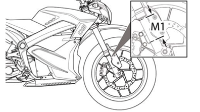
(d) Remove the motorcycle from the stand.
(e) Wearing your normal riding apparel, sit on the motorcycle.
(f) Have an assistant hold the motorcycle upright, your feet should be on both pegs.
(g) Bounce the suspension a couple of times.
(h) Have a second assistant take a measurement using the same locations as in step b.

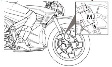
(i) Record this measurement (this is the measurement referred to as M2).
(j) Subtract the second measurement (M2) from the first measurement (M1).
2. Rebound Damping
The rebound damping is adjusted by turning the slotted brass adjuster screw (1) on the top of both fork legs. Next to it will be the writing S-F, meaning Slow and Fast. The adjuster has 9 stages of adjustment. This determines how quickly the fork returns to its extended position after being compressed. Turning the rebound adjuster screw clockwise will slow the rebound speed down making it better for larger, rolling terrain or bumps. Turning the rebound adjuster screw counter-clockwise will increase the rebound speed making it better for smaller, rougher bumps. Adjust each fork leg evenly.

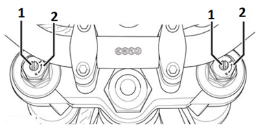
3. Compression Damping
The compression damping is adjusted by turning a screw (1) on the bottom of each fork leg. There is a rubber dust cover protecting the jam nut (1). Next to the screw are the letters “H” meaning Hard (slower compression) and “S” meaning Soft (faster compression). The adjuster has 12 stages of adjustment. Turn the adjuster counter-clockwise for slower compression. To speed up compression, turn the adjuster clockwise. Start with a middle setting and fine tune the compression from there. Proper compression will allow the tire to track the ground over consecutive bumps. Compression that is set too slow will pack-up (feel harsh over consecutive bumps) while compression that is set too fast will cause the fork to bottom out harshly. If the fork is bottoming out, turn the adjuster one turn at a time until the bottoming-out stops. Adjust each fork leg evenly.

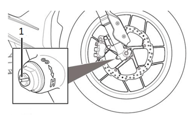
4. Spring Preload Adjustment

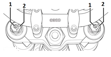
The spring preload is adjusted by turning the 19 mm anodized hex nut (2) located on top of the fork spring.
Note: When adjusting preload, always start from the minimum setting and adjust each fork leg evenly.
• Turning the adjustment nut clockwise increases the spring preload and reduces sag of the front suspension.
• Turning the adjustment nut counter-clockwise decreases the spring preload and increases sag of the front suspension.
Factory Supplied Front Suspension Settings
|
S ZF7.2 Models
|
|
|
Adjustment
|
Setting
|
|
Front Fork Compression
|
8 clicks counter-clockwise from maximum (H) position.
|
|
Front Fork Preload
|
7.5 turns clockwise from the full out position
|
|
Front Fork Rebound (tension)
|
9 clicks counter-clockwise from maximum (H) position
|
|
Front Sag
|
45 mm (1.77 in)
|
|
DS ZF7.2 Models
|
|
|
Front Fork Compression
|
7 clicks counter-clockwise from maximum (H) position.
|
|
Front Fork Preload
|
5.5 turns clockwise from the full out position
|
|
Front Fork Rebound (tension)
|
12 clicks counter-clockwise from maximum (H) position
|
|
Front Sag
|
59 mm (2.32 in)
|
|
S and SR ZF14.4 Models
|
|
|
Adjustment
|
Setting
|
|
Front Fork Compression
|
6 clicks counter-clockwise from maximum (H) position.
|
|
Front Fork Preload
|
7.5 turns clockwise from the full out position
|
|
Front Fork Rebound (tension)
|
9 clicks counter-clockwise from maximum (H) position.
|
|
Front Sag
|
45 mm (1.77 in)
|
|
DS and DSR ZF14.4 Models
|
|
|
Front Fork Compression
|
6 clicks counter-clockwise from maximum (H) position
|
|
Front Fork Preload
|
7.5 turns clockwise from the full out position.
|
|
Front Fork Rebound (tension)
|
11 clicks counter-clockwise from maximum (H) position.
|
|
Front Sag
|
59 mm (2.32 in)
|
Rear Shock Adjustment
Adjusters should never be forced completely in one direction; always leave on click of adjustment in either direction.
Spring Adjustment
Obtaining the correct rear spring rate is critical for proper handling. The spring rate must be set to match the weight of the rider. The spring is preloaded for an 82 kg (180 lb) rider. Heavier riders require stiffer spring rates. A good approximation of the rear spring requirements can be found by measuring the rear suspension’s sag. This measurement will quickly determine if the rear spring is approximately correct for the rider's weight. This adjustment is a recommendation guideline; personal riding preference may vary from the specifications given.
• Checking Sag
1. Support the motorcycle on a stand with the rear wheel off the ground.
2. Measure vertically from the rear axle to the rear fender; mark this spot as it will be used for other measurements.
3. Record this measurement; this will be measurement M1.

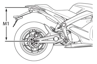
4. Remove the motorcycle from the stand.
5. Wearing normal riding apparel, sit on the motorcycle.
6. Have an assistant hold the motorcycle up, your feet should be on both pegs.
7. Bounce the suspension a couple of times.
8. Have a second assistant take a measurement using the same locations as in step 2.
9. Record this measurement; this will be measurement M2.

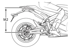
10. Subtract the second measurement (M2) from the first measurement (M1).
Example:
|
M1
|
|
105 mm (4.13 in)
|
|
M2
|
-
|
60 mm (2.36 in)
|
|
Sag
|
=
|
45 mm (1.77 in)
|
The total sag is 45 mm (1.77 in). Refer to the chart below for the correct sag. If the sag is not correct the spring pre-load should be adjusted. Refer Spring Pre-load Adjustment.
Preferred settings
|
MODEL
|
SAG
|
|
S and SR
|
45 mm (1.77 in)
|
|
DS and DSR
|
60 mm (2.36 in)
|
Spring Pre-load Adjustment
1. Clean any dirt or debris from the slots of the shock adjusting collar (1).
2. Using a lock ring wrench turn the adjusting collar (1).
3. For measurements less than the specified value, decrease the pre-load on the spring by turning the adjustment collar counter-clockwise on the shock. If more than the specified value, increase the pre-load on the spring by turning the adjustment collar clockwise on the shock.

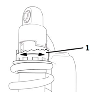
Rebound Adjustment
The rebound adjuster knob (1) is at the bottom of the shock. It has 8 stages of adjustment. Printed on the knob is H-S, meaning Hard and Slow. The rebound adjuster knob controls how slow or fast the shock returns to its extended position after being compressed. Turning the knob clockwise, or S direction, is good for big impacts. Turning the knob counterclockwise, or S direction, is good for many smaller and more frequent impacts.

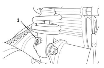
Compression Adjustment
The compression adjustment knob (1) is at the top of the shock. It has 18 stages of adjustment. Printed on the knob is “H” meaning Hard (slower compression) and “S” meaning Soft (faster compression). Turn the adjuster clockwise for slower compression. To speed up compression, turn the adjuster counter-clockwise. Start with a middle setting and fine tune the compression from there. Proper compression will allow the tire to track the ground over consecutive bumps. Compression that is set too slow will pack-up (feel harsh over consecutive bumps) while compression that is set too fast will cause the shock to bottom out harshly. If the shock is bottoming out, turn the adjuster one click at a time until the bottom out stops.

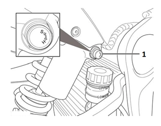
Factory Supplied Rear Suspension Settings
|
S ZF7.2 Models
|
|
|
Adjustment
|
Setting
|
|
Rear Shock Compression
|
14 clicks counter-clockwise from maximum (H) position.
|
|
Rear Shock Rebound (tension)
|
9 clicks counter-clockwise from maximum (H) position.
|
|
Rear Shock Spring Preload
|
5th position from minimum unloaded position.
|
|
DS ZF7.2 Models
|
|
|
Rear Shock Compression
|
10 clicks counter-clockwise from maximum (H) position.
|
|
Rear Shock Rebound (tension)
|
12 clicks counter-clockwise from maximum (H) position.
|
|
Rear Shock Spring Preload
|
5th position from minimum unloaded position.
|
|
S and SR ZF14.4 Models
|
|
|
Adjustment
|
Setting
|
|
Rear Shock Compression
|
12 clicks counter-clockwise from maximum (H) position.
|
|
Rear Shock Rebound (tension)
|
6 clicks counter-clockwise from maximum (H) position.
|
|
Rear Shock Spring Preload
|
5th position from minimum unloaded position.
|
|
DS and DSR ZF14.4 Models
|
|
|
Rear Shock Compression
|
13 clicks counter-clockwise from maximum (H) position.
|
|
Rear Shock Rebound (tension)
|
8 clicks counter-clockwise from maximum (H) position.
|
|
Rear Shock Spring Preload
|
5th position from minimum unloaded position.
|
Version 1
Suspension
Description and Operation
The front and rear suspension can be adjusted for sag and damping. For adjustment procedures, refer to Suspension Adjustment.
Front Suspension
The fork assembly contains the triple tree and fork legs (shocks). The triple tree holds the fork legs in place and attaches the fork assembly to the frame.
The shock has two main actions: Compression when the shock gets
compressed, and rebound when the shock returns back to full length.
Compression damping is the adjustment that determines how fast or slow
the fork compresses. Rebound damping is the adjustment that determines
how fast or slow the fork rebounds.
Rear Suspension
The rear suspension is a swingarm with a monoshock design. One end of the swingarm is connected to the frame (pivot end) and the end to the wheel. Controlling the action/movement of the swingarm is the shock.
The shock is a fully adjustable coilover design. The coilover shock contains a spring surrounding it. The spring rate is adjustable and is factory set for a 82 kg (180 lb) rider. The rate is a measure of how much force is required to compress the spring a given distance. The higher the rate, the more force it takes to compress it a given distance, and the less it compresses under a given force.
The shock has two main actions: Compression when the shock gets compressed, and rebound when the shock returns back to full length. Compression damping is the adjustment that determines how fast or slow the shock compresses. Rebound damping is the adjustment that determines how fast or slow the shock rebounds.
Version 1
| Torque settings for: Steering Head Service | |
| Item | Torque Setting |
| Steering Stem Lock Nut | 34 N•m (25 lb ft) |
| Lower Triple Clamp Pinch Bolts | 23 N•m (17 lb ft) |
| Steering Stem Nut | 81 N•m (60 lb ft) |
| Upper Triple Clamp Pinch Bolts | 20 N•m (15 lb ft) |
| Handlebar Clamp Bolts | 26 N•m (19 lb ft) |
| Front Axle Shaft | 54 N•m (40 lb ft) |
| Front Axle Shaft Pinch Bolts | 12 N•m (9 lb ft) |
| Front Brake Caliper Bolts | 26 N•m (19 lb ft) |
| Lower Headlamp Bracket Bolts | 5 N•m (48 lb in) |
 Show Torque Table
Required Tools
• 17mm wrench
• Steering stem lock nut socket
• 16mm hex wrench
• 41mm socket
• 6mm hex wrench
• 5mm hex wrench
• 3mm hex wrench
Replacement Parts
• Dust seals
• Lower Triple Clamp Assembly – S/DS/SR/DSR
Fastener Torques
Notice: Refer to Fastener Notice in General Information.
• Steering stem lock nut to 34 N•m (25 lb ft)
• Lower triple clamp pinch bolts* to 23 N•m (15 lb ft)
• Steering stem nut to 81 N•m (60 lb ft)
• Upper triple clamp pinch bolts* to 20 N•m (15 lb ft)
• Handlebar clamp bolts to 26 N•m (19 lb ft)
• Front axle shaft** to 54 N•m (40 lb ft)
• Front axle shaft pinch bolts* 12 N•m (9 lb ft)
• Front brake caliper bolts to 26 N•m (19 lb ft)
• Lower headlamp bracket bolts to 5 N•m (48 lb in)
*Use LOCTITE® 242® (or equivalent)
**Use Anti-Seize (or equivalent)
Exploded View

Legend:
1. Steering Stem Nut
2. Washer
3. Upper Triple Clamp
4. Steering Stem Lock Nut
5. Dust Seal
6. Bearing and Inner Race
7. Bearing
8. Dust Seal
9. Lower Triple Clamp
Removal Procedure
1. Remove the key from the key switch and support the motorcycle upright on a stand with the front wheel off the ground.
2. Remove the 2 caliper bolts (1). Support the brake caliper (2) with mechanic's wire, or equivalent, whenever it is separated from its mount and the hydraulic flexible brake hose is still connected. Failure to support the caliper in this manner will cause the flexible brake hose to bear the weight of the caliper, which may cause damage to the brake hose and in turn may cause a brake fluid leak.

3. Slide the brake caliper off of the brake rotor and support the brake caliper with mechanic's wire or equivalent. DO NOT disconnect the hydraulic brake hose from the brake caliper.
4. Remove the front axle shaft pinch bolts (2) from the right lower fork leg.
5. Unscrew the front axle (1) then slide the axle out of the fork.

6. Remove sensor wire/brake line clamp from fork guard.
7. Remove the front fender (PAINTED S/SR FRONT FENDER YELLOW #3, PAINTED S/SR FRONT FENDER WHITE #3, PAINTED S/SR FRONT FENDER BLACK #3, PAINTED S/SR FRONT FENDER RED #3, FRONT FENDER DIRT BRAKE LINE HOLE).
8. Remove the lower headlight bolts (1) from both sides.
9. Remove the lower headlight bracket bolts (2) from both sides and the bracket (3).
10. Loosen the lower triple clamp pinch bolts (4) from both sides.

11. Remove the left upper headlight bracket bolts (1) and then remove the right headlight bracket bolts.

12. Hang the headlight and instrument panel assembly forward of the motorcycle and cover them to protect from damage.
13. Remove handlebar bolts (1), clamps, and the handlebar. Lay forward on headlight and instrument panel assembly.
14. Loosen the upper triple clamp pinch bolts (2).
15. Remove steering stem nut and washer (3).

16. Remove upper triple clamp. Place towel between triple clamp and handlebar for protection.
17. Remove both of the forks (S FORK 41MM LEFT, S FORK 41MM RIGHT, DS FORK 41MM LEFT, DS FORK 41MM RIGHT) from lower triple clamp.
18. Using a steering stem nut socket (1) remove steering stem lock nut.

19. Remove lower triple clamp assembly from frame.
20. Remove all bearings and dust seals.

Inspection Procedure
1. Clean head tube bore completely.
2. Clean bearing races and steering stem with brake cleaner or alcohol.
3. Inspect steering stem just above the lower inner race for scoring/gouging of steering stem.
If you find scoring or damage to steering stem, you must replace the lower triple clamp assembly, bearings, and races. If the bearing races are loose in the head tube bores, the frame must be replaced.
If scoring/pitting or any other damage is found on the bearings or races, the bearing and races must be replaced.
Bearing Race Replacement
Removal Procedure
The bearing race is pressed into the head tube bore. To remove the race, insert a soft punch into the head tube and carefully tap the race out from the inside. There are notches (1) in the head tube for the punch to get the race started. After it is started, tap around the race to get it out evenly without damaging the head tube bore.
Note: When the race is removed, it can score the head tube bore. Inspect the head tube bore area (2) for any damage. If any damage is found, smooth bore with 600 grit sandpaper to remove scores or ridges.

Installation Procedure
1. Apply Loctite® 609® to sides and bottom of outer race and sides and bottom of head tube bore.
2. Tap the race in slowly and evenly with a race installer or suitable socket. Make sure that the race is squarely seated in the head set bore before tapping it in. Ensure that the race is fully seated in the head tube bore.
3. Wipe residual green Loctite® 609® from race and head tube.
Installation Procedure
1. Fully pack the bearings with grease. You MUST thoroughly work the grease into the bearings, between the rollers, the core, and the cage.
2. Install the lower dust seal (1) on the steering stem.
3. Apply Loctite® 609® to steering stem (2) and inner race.
4. Slip the inner race (3) onto stem and rotate 2 full turns to evenly distribute Loctite.

5. Wipe clean any residual Loctite.
6. Install upper bearing (1) and upper inner race (2) into top head tube bore.

7. Install the upper dust seal (1).

8. Install lower bearing (1) onto the steering stem.

9. Install lower triple clamp assembly into head tube.
Note: Install steering stem lock nut with bevel side down. Take care to keep centered, upward force on lower triple clamp while installing steering stem lock nut so that it is hand-tight. Rotate lower triple clamp and feel for smooth rotation.
Notice: Refer to Fastener Notice in General Information.
10. Using a steering stem lock nut socket tighten the steering stem lock nut to 68 N•m (50 lb ft) and then back off the nut so that it is hand-tight.
11. Then tighten the steering stem lock nut.
Tighten
Steering stem lock nut to 34 N•m (25 lb ft)
12. Rotate lower triple clamp assembly and feel for smooth rotation again.
13. Install upper triple clamp onto steering stem.
14. Check that the routing of brake lines and harness is correct.
15. Install the top washer (2) and nut (1) onto steering stem and leave loose.

16. Install forks into triple clamps.
17. Set the top of forks 10mm (A) from the top of upper triple clamp bore.

18. Apply LOCTITE® 242® and tighten the lower triple clamp pinch bolts.
Tighten
Lower triple clamp bolts to 23 N•m (17 lb ft)
19. Tighten the steering stem nut (3).
Tighten
Steering stem nut to 81 N•m (60 lb ft)
20. Apply LOCTITE® 242® and tighten the upper triple clamp pinch bolts (2).
Tighten
Upper triple clamp pinch bolts to 20 N•m (15 lb ft)
21. Install the handlebar, clamps and bolts (1).
Tighten
Handlebar clamp bolts to 27 N•m (20 lb ft)

22. Install headlamp and instrument panel assembly. Ensure the C239 ground is installed.
23. Install headlamp lower bracket.
Tighten
Lower headlamp bracket bolts to 5 N•m (48 lb in)
24. Install the front fender.
25. Install front wheel assembly.
26. Be sure to orient wheel speed sensor to avoid breaking tab (1) on sensor hub.

27. Apply Anti-Seize (or equivalent) and install the front axle shaft (1).
Tighten
Front axle shaft to 54 N•m (40 lb ft)
28. Verify that the wheel speed sensor has not moved after torqueing axle shaft.
29. Apply LOCTITE® 242® to the front axle pinch bolts (2).
Tighten
Front axle shaft pinch bolts to 12 N•m (9 lb ft)

30. Apply LOCTITE® 242® to the brake caliper bolts.
31. Install the front brake caliper (2) and bolts (1). Ensure that the brake pads are centered on the brake rotor.
Tighten
Front brake caliper bolts to 26 N•m (19 lb ft)

32. Install ABS sensor wire and brake line clamps in the same locations as removed.
33. Let the motorcycle sit for no less than 12 hours to allow Loctite to cure.
34. Road test the motorcycle to ensure that the condition has been corrected. Refer to Road Testing Procedure.
Version 1
| Torque settings for: Swingarm Assembly Replacement-Belt | |
| Item | Torque Setting |
| Swingarm Pivot Bolts | 102 N•m (75 lb ft) |
| Axle Shaft Nut | 102 N•m (75 lb ft) |
| Brake Pedal Pivot Bolt | 46 N•m (34 lb ft) |
 Show Torque Table
Required Tools
• 3mm hex wrench
• 27mm socket and socket wrench
• 10mm hex wrench
• 15mm wrench
• 17mm wrench
Fastener torques
Notice: Refer to Fastener Notice in General Information
• Swingarm pivot bolts 102 N•m (75 lb ft)
• Shock nut and bolt 54 N•m (40 lb ft)
• Brake pedal pivot bolt* to 46 N•m (34 lb ft)
• Axle shaft nut* to 102 N•m (75 lb ft)
*Use LOCTITE® 242® (or equivalent)
Removal Procedure
Note: The location of the swingarm ground strap and brake line clips, before removing the rear fender.
1. Remove the 4 bolts securing the rear fender to the swingarm, and remove the fender or fender.
2. Securely raise and support the motorcycle so that the rear wheel is off the ground.
3. Remove the rear axle nut (1) and tap out the axle shaft. Note: There is an axle shaft spacer on the left side of the wheel.

4. Lower the wheel and remove the drive belt from the sprocket.
Important: Support the brake caliper with mechanic's wire, or equivalent, whenever it is separated from its mount and the hydraulic flexible brake hose is still connected. Failure to support the caliper in this manner will cause the flexible brake hose to bear the weight of the caliper, which may cause damage to the brake hose and in turn may cause a brake fluid leak.
5. Move and support the brake caliper with mechanic's wire or equivalent. DO NOT disconnect the hydraulic brake hose from the brake caliper.
6. Remove the brake pedal pivot bolt.
7. Remove the shock lower nut and bolt.
8. Remove the protective rubber cap and pivot bolt (1). Right side shown, left side similar.
9. Remove the swingarm assembly.

Installation Procedure
1. Place the swingarm assembly into position.
Notice: Refer to Fastener Notice in General Information
2. Install the swingarm pivot bolts (1) and tighten. Right side shown, left side similar.
Tighten
Swingarm pivot bolts to 102 N•m (75 lb ft)

3. Install the protective rubber caps.
4. Install the shock lower nut and bolt.
Tighten
Shock nut and bolt to 54 N•m (40 lb ft)
5. Install the brake pedal pivot bolt.
Tighten
Brake pedal pivot bolt to 46 N•m (34 lb ft)
6. Place the caliper into position on the swingarm.
7. Place the drive belt onto the wheel sprocket, ensuring that the left wheel spacer is in place.
8. Move the wheel into position. Ensure that the brake rotor is centered between the brake pads, and the ABS sensor is in place.
9. Slide the axle shaft (2) through the swingarm and wheel and install the nut (1).
Tighten
Axle shaft nut to 102 N•m (75 lb ft)
10. Install the fender, ground strap and brake line clips onto the swingarm.

Version 1
Front Fork Adjustment
Adjusters should never be forced completely in one direction; always leave one click of adjustment in either direction.
1. Fork Preload (sag)
(a) Support the motorcycle upright on a stand with the front wheel on the ground.
(b) Measure vertically from the bottom of the fork tube to the bottom of the tube’s dust seal.
(c) Record this measurement (this is the measurement referred to as M1).


(d) Remove the motorcycle from the stand.
(e) Wearing your normal riding apparel, sit on the motorcycle.
(f) Have an assistant hold the motorcycle upright, your feet should be on both pegs.
(g) Bounce the suspension a couple of times.
(h) Have a second assistant take a measurement using the same locations as in step b.


(i) Record this measurement (this is the measurement referred to as M2).
(j) Subtract the second measurement (M2) from the first measurement (M1).
2. Rebound Damping
The rebound damping is adjusted by turning the slotted brass adjuster screw (1) on the top of both fork legs. Next to it will be the writing S-F, meaning Slow and Fast. The adjuster has 9 stages of adjustment. This determines how quickly the fork returns to its extended position after being compressed. Turning the rebound adjuster screw clockwise will slow the rebound speed down making it better for larger, rolling terrain or bumps. Turning the rebound adjuster screw counter-clockwise will increase the rebound speed making it better for smaller, rougher bumps. Adjust each fork leg evenly.


3. Compression Damping
The compression damping is adjusted by turning a screw (1) on the bottom of each fork leg. There is a rubber dust cover protecting the jam nut (1). Next to the screw are the letters “H” meaning Hard (slower compression) and “S” meaning Soft (faster compression). The adjuster has 12 stages of adjustment. Turn the adjuster counter-clockwise for slower compression. To speed up compression, turn the adjuster clockwise. Start with a middle setting and fine tune the compression from there. Proper compression will allow the tire to track the ground over consecutive bumps. Compression that is set too slow will pack-up (feel harsh over consecutive bumps) while compression that is set too fast will cause the fork to bottom out harshly. If the fork is bottoming out, turn the adjuster one turn at a time until the bottoming-out stops. Adjust each fork leg evenly.


4. Spring Preload Adjustment


The spring preload is adjusted by turning the 19 mm anodized hex nut (2) located on top of the fork spring.
Note: When adjusting preload, always start from the minimum setting and adjust each fork leg evenly.
• Turning the adjustment nut clockwise increases the spring preload and reduces sag of the front suspension.
• Turning the adjustment nut counter-clockwise decreases the spring preload and increases sag of the front suspension.
Factory Supplied Front Suspension Settings
|
S ZF7.2 Models
|
|
|
Adjustment
|
Setting
|
|
Front Fork Compression
|
8 clicks counter-clockwise from maximum (H) position.
|
|
Front Fork Preload
|
7.5 turns clockwise from the full out position
|
|
Front Fork Rebound (tension)
|
9 clicks counter-clockwise from maximum (H) position
|
|
Front Sag
|
45 mm (1.77 in)
|
|
DS ZF7.2 Models
|
|
|
Front Fork Compression
|
7 clicks counter-clockwise from maximum (H) position.
|
|
Front Fork Preload
|
5.5 turns clockwise from the full out position
|
|
Front Fork Rebound (tension)
|
12 clicks counter-clockwise from maximum (H) position
|
|
Front Sag
|
59 mm (2.32 in)
|
|
S and SR ZF14.4 Models
|
|
|
Adjustment
|
Setting
|
|
Front Fork Compression
|
6 clicks counter-clockwise from maximum (H) position.
|
|
Front Fork Preload
|
7.5 turns clockwise from the full out position
|
|
Front Fork Rebound (tension)
|
9 clicks counter-clockwise from maximum (H) position.
|
|
Front Sag
|
45 mm (1.77 in)
|
|
DS and DSR ZF14.4 Models
|
|
|
Front Fork Compression
|
6 clicks counter-clockwise from maximum (H) position
|
|
Front Fork Preload
|
7.5 turns clockwise from the full out position.
|
|
Front Fork Rebound (tension)
|
11 clicks counter-clockwise from maximum (H) position.
|
|
Front Sag
|
59 mm (2.32 in)
|
Rear Shock Adjustment
Adjusters should never be forced completely in one direction; always leave on click of adjustment in either direction.
Spring Adjustment
Obtaining the correct rear spring rate is critical for proper handling. The spring rate must be set to match the weight of the rider. The spring is preloaded for an 82 kg (180 lb) rider. Heavier riders require stiffer spring rates. A good approximation of the rear spring requirements can be found by measuring the rear suspension’s sag. This measurement will quickly determine if the rear spring is approximately correct for the rider's weight. This adjustment is a recommendation guideline; personal riding preference may vary from the specifications given.
• Checking Sag
1. Support the motorcycle on a stand with the rear wheel off the ground.
2. Measure vertically from the rear axle to the rear fender; mark this spot as it will be used for other measurements.
3. Record this measurement; this will be measurement M1.


4. Remove the motorcycle from the stand.
5. Wearing normal riding apparel, sit on the motorcycle.
6. Have an assistant hold the motorcycle up, your feet should be on both pegs.
7. Bounce the suspension a couple of times.
8. Have a second assistant take a measurement using the same locations as in step 2.
9. Record this measurement; this will be measurement M2.


10. Subtract the second measurement (M2) from the first measurement (M1).
Example:
|
M1
|
|
105 mm (4.13 in)
|
|
M2
|
-
|
60 mm (2.36 in)
|
|
Sag
|
=
|
45 mm (1.77 in)
|
The total sag is 45 mm (1.77 in). Refer to the chart below for the correct sag. If the sag is not correct the spring pre-load should be adjusted. Refer Spring Pre-load Adjustment.
Preferred settings
|
MODEL
|
SAG
|
|
S and SR
|
45 mm (1.77 in)
|
|
DS and DSR
|
60 mm (2.36 in)
|
Spring Pre-load Adjustment
1. Clean any dirt or debris from the slots of the shock adjusting collar (1).
2. Using a lock ring wrench turn the adjusting collar (1).
3. For measurements less than the specified value, decrease the pre-load on the spring by turning the adjustment collar counter-clockwise on the shock. If more than the specified value, increase the pre-load on the spring by turning the adjustment collar clockwise on the shock.


Rebound Adjustment
The rebound adjuster knob (1) is at the bottom of the shock. It has 8 stages of adjustment. Printed on the knob is H-S, meaning Hard and Slow. The rebound adjuster knob controls how slow or fast the shock returns to its extended position after being compressed. Turning the knob clockwise, or S direction, is good for big impacts. Turning the knob counterclockwise, or S direction, is good for many smaller and more frequent impacts.


Compression Adjustment
The compression adjustment knob (1) is at the top of the shock. It has 18 stages of adjustment. Printed on the knob is “H” meaning Hard (slower compression) and “S” meaning Soft (faster compression). Turn the adjuster clockwise for slower compression. To speed up compression, turn the adjuster counter-clockwise. Start with a middle setting and fine tune the compression from there. Proper compression will allow the tire to track the ground over consecutive bumps. Compression that is set too slow will pack-up (feel harsh over consecutive bumps) while compression that is set too fast will cause the shock to bottom out harshly. If the shock is bottoming out, turn the adjuster one click at a time until the bottom out stops.


Factory Supplied Rear Suspension Settings
|
S ZF7.2 Models
|
|
|
Adjustment
|
Setting
|
|
Rear Shock Compression
|
14 clicks counter-clockwise from maximum (H) position.
|
|
Rear Shock Rebound (tension)
|
9 clicks counter-clockwise from maximum (H) position.
|
|
Rear Shock Spring Preload
|
5th position from minimum unloaded position.
|
|
DS ZF7.2 Models
|
|
|
Rear Shock Compression
|
10 clicks counter-clockwise from maximum (H) position.
|
|
Rear Shock Rebound (tension)
|
12 clicks counter-clockwise from maximum (H) position.
|
|
Rear Shock Spring Preload
|
5th position from minimum unloaded position.
|
|
S and SR ZF14.4 Models
|
|
|
Adjustment
|
Setting
|
|
Rear Shock Compression
|
12 clicks counter-clockwise from maximum (H) position.
|
|
Rear Shock Rebound (tension)
|
6 clicks counter-clockwise from maximum (H) position.
|
|
Rear Shock Spring Preload
|
5th position from minimum unloaded position.
|
|
DS and DSR ZF14.4 Models
|
|
|
Rear Shock Compression
|
13 clicks counter-clockwise from maximum (H) position.
|
|
Rear Shock Rebound (tension)
|
8 clicks counter-clockwise from maximum (H) position.
|
|
Rear Shock Spring Preload
|
5th position from minimum unloaded position.
|
Version 1
Suspension
Description and Operation
The front and rear suspension can be adjusted for sag and damping. For adjustment procedures, refer to Suspension Adjustment.
Front Suspension
The fork assembly contains the triple tree and fork legs (shocks). The triple tree holds the fork legs in place and attaches the fork assembly to the frame.
The shock has two main actions: Compression when the shock gets
compressed, and rebound when the shock returns back to full length.
Compression damping is the adjustment that determines how fast or slow
the fork compresses. Rebound damping is the adjustment that determines
how fast or slow the fork rebounds.
Rear Suspension
The rear suspension is a swingarm with a monoshock design. One end of the swingarm is connected to the frame (pivot end) and the end to the wheel. Controlling the action/movement of the swingarm is the shock.
The shock is a fully adjustable coilover design. The coilover shock contains a spring surrounding it. The spring rate is adjustable and is factory set for a 82 kg (180 lb) rider. The rate is a measure of how much force is required to compress the spring a given distance. The higher the rate, the more force it takes to compress it a given distance, and the less it compresses under a given force.
The shock has two main actions: Compression when the shock gets compressed, and rebound when the shock returns back to full length. Compression damping is the adjustment that determines how fast or slow the shock compresses. Rebound damping is the adjustment that determines how fast or slow the shock rebounds.
Version 1
|
Application
|
Specification
|
|
|
Metric
|
English
|
|
|
Banjo Bolt
|
31 N•m
|
23 lb ft
|
|
Caliper Bleeder Valve
|
7 N•m
|
62 lb in
|
|
Front Brake Caliper Bolts*
|
26 N•m
|
19 lb ft
|
|
Front Brake Rotor Bolt
|
26 N•m
|
19 lb ft
|
|
Rear Axle Shaft Nut*
|
102 N•m
|
75 lb ft
|
|
Rear Brake Caliper Slide Pin*
|
46 N•m
|
34 lb ft
|
|
Rear Brake Rotor Bolts*
|
13 N•m
|
9.5 lb ft
|
|
Front Axle Pinch Bolts*
|
12 N•m
|
9 lb ft
|
|
Seat Bolts
|
22 N•m
|
16 lb ft
|
|
Rear Tank Bolts
|
5 N•m
|
44 lb in
|
|
Front Fairing Screws
|
2 N•m
|
18 lb in
|
|
Front Tank Bolts
|
4 N•m
|
35 lb in
|
|
ABS HCU Bolts
|
6 N•m
|
72 lb in
|
|
Front Fender Bolts DS
|
3 N•m
|
24 lb in
|
|
Front Fender Bolts S/SR
|
11 N•m
|
8 lb ft
|
|
Front Axle Shaft**
|
54 N•m
|
40 lb ft
|
*Use LOCTITE® 242® (or equivalent)
**Use Anti-Seize (or equivalent)
Version 1
|
Causes |
Correction |
| Sticky caliper or caliper pistons | Replace the caliper. |
| Contaminated or improper brake fluid | Flush the brake system and repair the affected brake components. |
| Loose front or rear brake assembly components | Locate and tighten the loose brake components. |
| Brake lever/pedal binding | Repair or replace the brake lever/pedal. |
Version 1
|
Cause |
Correction |
| Linings damaged by abusive use | Replace the brake linings. |
| Poor rotor surface finish | Replace the rotor. |
Version 1
|
Causes |
Correction |
| Worn out brake linings | Replace the brake linings. |
| Incorrect lining material | Replace the brake linings. |
| Contaminated brake linings | Replace the brake linings. |
| Linings damaged by abusive use | Replace the brake linings. |
| Scored rotor | Replace the rotor. |
Version 1
|
Causes |
Correction |
| Loose front or rear suspension parts | Locate and tighten, repair or replace the loose front or rear suspension components. |
| Worn out brake linings | Replace the brake linings. |
| Uneven brake lining material | Replace the brake linings. |
| Contaminated brake linings | Replace the brake linings. |
| Linings damaged by abusive use | Replace the brake linings. |
Scraping Noise
|
Causes |
Correction |
| Loose front suspension parts | Locate and tighten, repair or replace the loose front or rear suspension components. |
|
• Worn out brake linings
|
Replace the brake linings. |
|
• Contaminated brake lining
|
Replace the brake linings. |
|
• Linings damaged by abusive use
|
Replace the brake linings. |
|
• Front or rear brake assembly components loose
|
Locate and tighten the loose brake components. |
Chatter/Roughness
|
Causes |
Correction |
|
• Scored rotor
|
Replace the rotor. Inspect and replace brake linings if necessary. |
|
• Improper thickness variation in rotor
|
Replace the rotor. |
|
• Excessive rotor lateral runout
|
Replace the rotor. |
|
• Loose front or rear brake assembly components
|
Locate and tighten the loose brake components. |
Version 1
|
Causes |
Correction |
| Contaminated or improper brake fluid | Flush the brake system and repair the affected brake components. |
| Sticky caliper or caliper pistons | Replace the caliper. |
Version 1
|
Causes |
Correction |
| Glazed brake linings | Replace the brake linings. |
| Worn out brake linings | Replace the brake linings. |
| Incorrect lining material | Replace the brake linings. |
| Contaminated brake linings | Replace the brake linings. |
| Linings damaged by abusing use | Replace the brake linings. |
| Restricted brake fluid passage | Locate and repair the brake fluid passage restriction. |
| Brake lever/pedal interference or binding | Repair or replace the brake lever/pedal. |
Version 1
|
Causes |
Correction |
| Air in the brake system | Bleed the brake system. |
| Leaking brake hose or connection | Locate and repair the brake hose or the connection. |
| Leaking caliper piston seal | Replace the caliper. |
| Leaking master cylinder (internally) | Replace the master cylinder. |
| Contaminated/improper brake fluid | Flush the brake system and repair the affected brake components. |
| Loose front or rear brake assembly components | Locate and tighten loose brake components. |
Version 1
If a malfunction occurs in the ABS system, the amber ABS warning indicator will turn on during the ignition cycle during which the malfunction is detected.
A diagnostic trouble code will store under the following conditions:
• The malfunction is current
• The malfunction is intermittent
The diagnostic codes are held in the system and require a special cable to connect to it and retrieve the trouble codes.
Diagnostics Trouble Code (DTC) List
TBD
Version 1
The following procedure is used to check the ABS system. This will allow you to read DTC faults, clear DTC faults, read data, and program this system.
1. On a computer with Tera Term installed, connect the USB A-B cable to the computer, and the other end to the C3 OBD-II (data link) connector.
Launching the ABS Scan Tool
1. Power ON the motorcycle.
2. Find this icon on your desktop. Click the icon to start the program.


3. After clicking the icon, the folder below will open. Click on the “PROGRAMMING ROOT” selection.

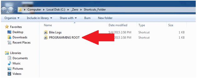
4. This will open a folder of selectable model years (MY). Select the MY motorcycle you are connected to. NOTE: 2015 is the first year ABS was offered.

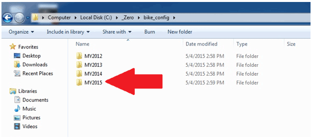
5. This will open folders of selectable modules. Click on the ABS folder.

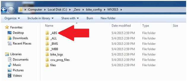
6. This will open up a CAN folder. Click on the folder.

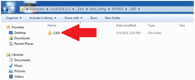
7. This will open up different batch files; the 3 that you will use for the ABS system are:
• ABS_CLEAR_DTCS
• ABS_MENU
• ABS_READ_DTCS

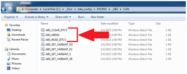
Clearing DTC Codes
1. Click on the ABS_CLEAR_DTCS selection.

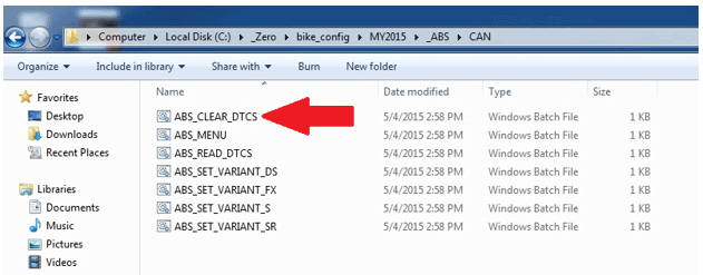
2. You may get an Open File – Security Warning. If you do, click the Run button.

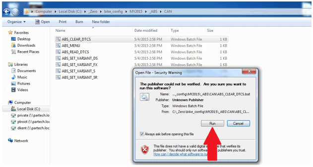
3. This will open up a command prompt window with information about clearing the DTC’s.

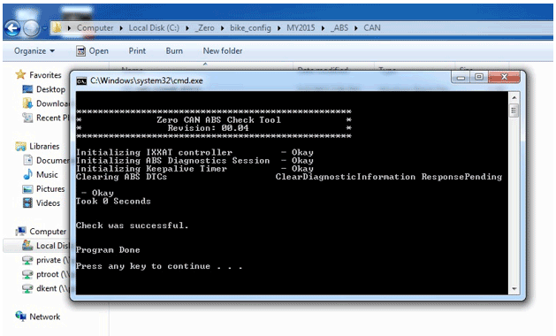
ABS Check Main Menu
1. Click on the ABS_MENU selection.

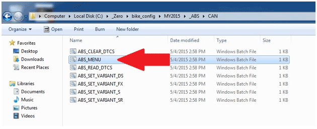
2. You may get an Open File – Security Warning. If you do, click the Run button.

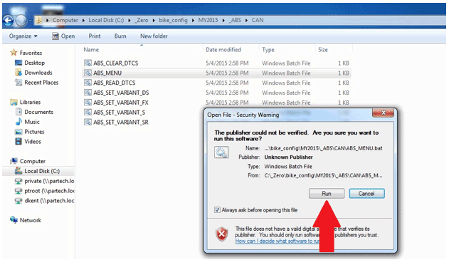
3. This will open up a command prompt window with different selections.

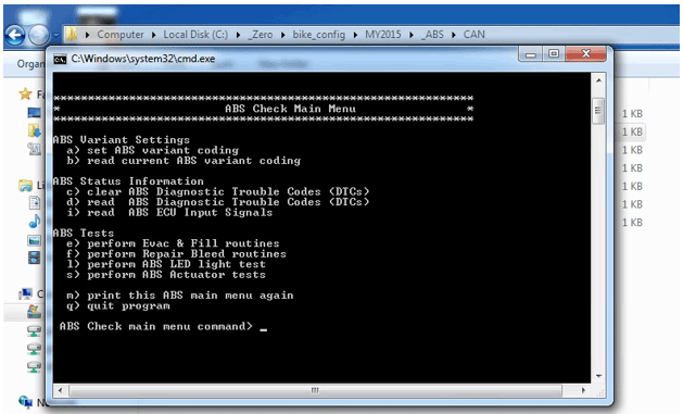
At this point you can select from the titles (B) within the command prompt window. By selecting the letter next to the title (A) and typing it in at the curser area (C), the information within that title will display.

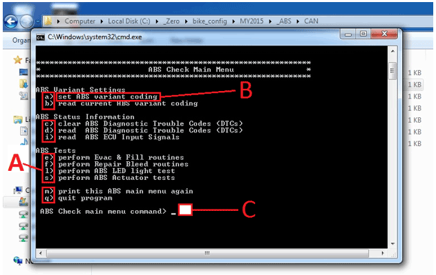
Example: If set ABS variant coding is selected (A), the bottom of the command prompt window will display all the information (B) within that title. Note: this window is scrollable using the slide button on the right of the window.

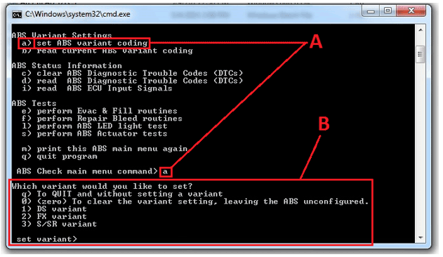
Reading ABS Diagnostic Trouble Codes (DTCS)
1. Click on the ABS_READ_DTCS selection.

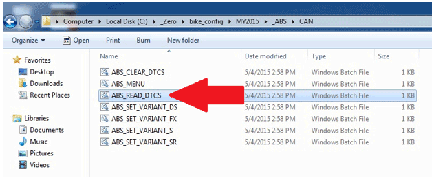
2. You may get an Open File – Security Warning. If you do, click the Run button.

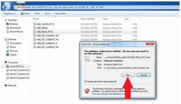
3. This will open a command prompt window with information about any DTCs that are set.

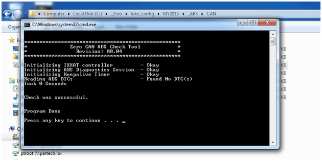
Version 1
Brake Pad Inspection
The brake pads must be
inspected when specified in the maintenance schedule. Visually inspect
the brakes by looking at the remaining brake pad material through the
sides of the brake caliper.
Replace the brake pads if either pad’s
thickness is 0.053 in (1.35 mm) or less. If the brake pads are worn,
replace both brake pads immediately.
Brake Disc Inspection
The thickness of the brake discs should be checked
regularly. The minimum thickness is 0.14 in (3.50 mm).
Version 1
| Torque settings for: Brake Pad Replacement-Front | |
| Item | Torque Setting |
| Front Brake Caliper Bolts | 26 N•m (19 lb ft) |
 Show Torque Table
Required Tools
• Flat blade screwdriver
• T25 star socket
• 8mm hex wrench
Fastener Torques
Notice: Refer to Fastener Notice in General Information.
• Front brake caliper bolts* to 26 N•m (19 lb ft)
*Use LOCTITE® 242® (or equivalent)
Removal Procedure
1. Remove the 2 caliper bolts (1).
Support the brake caliper (2) with mechanic's wire, or equivalent, whenever it is separated from its mount, and the hydraulic flexible brake hose is still connected. Failure to support the caliper in this manner will cause the flexible brake hose to bear the weight of the caliper, which may cause damage to the brake hose and in turn may cause a brake fluid leak.
2. Slide the brake caliper off of the brake rotor and support the brake caliper with mechanic's wire or equivalent. DO NOT disconnect the hydraulic brake hose from the brake caliper.

Important: To prevent dirt and other contaminants from entering the master cylinder, thoroughly clean the cover before removal.
3. Remove the two screws to release the cover from the front master cylinder reservoir.
Note: As the pistons are pushed back into the caliper, the fluid level may rise and overflow the reservoir. Watch the fluid level as the pistons are retracted and remove fluid from the reservoir if necessary.
4. Press in the inner and outer brake pads pushing the pistons back into their bores.
5. Remove the caliper slide pin clip (1).
6. Remove the caliper slide pin (2), and remove the brake pads (3) from the caliper.
7. Inspect the brake caliper and brake hardware and replace as needed.

Installation Procedure
1. Install the disc brake pads (3) to the brake caliper, making sure that the anti-rattle clip is in position.
2. Install the caliper slide pin (2) and tighten.
3. Install the caliper slide pin clip (1).

4. Slide the brake caliper onto the rotor, making sure that the disc brake pads are centered on the brake rotor.
Notice: Refer to Fastener Notice in General Information.
5. Install the front caliper bolts (1).
Tighten
Front brake caliper bolts to 26 N•m (19 lb ft)
Caution: After installation of new pads, and before moving motorcycle, pump the front brake lever to build brake system pressure. Insufficient pressure can adversely affect brake performance, which could result in death or serious injury.
6. Verify that the brake fluid level is full. Add DOT 4 brake fluid, if necessary.
7. Install master cylinder reservoir cover.
Caution: After completing repairs or bleeding the system, always test motorcycle brakes at low speed. If brakes are not operating properly or braking efficiency is poor, testing at a high speed could result in death or serious injury.
8. Gently use the brakes a few times at low speeds (less than 25 mph [40 km/h]) to develop proper braking friction. With new brake systems or just new pads, the first few braking applications will result in very little braking power.
9. Road test the motorcycle. Refer to Road Testing Procedure. If the brakes feel spongy, bleed the system.

Version 1
| Torque settings for: Brake Pad Replacement-Rear | |
| Item | Torque Setting |
| Brake Caliper Slide Pin | 46 N•m (34 lb ft) |
 Show Torque Table
Required Tools
• T25 star socket
Fastener Torques
• Brake caliper slide pin* 46 N•m (34 lb ft)
*Use LOCTITE® 242® (or equivalent)
Removal Procedure
Caution: Always replace brake pads in pairs. Never replace just one brake pad. Mismatched brake pads can lead to brake system damage and loss of braking performance, which could result in serious injury or death.
1. Remove the caliper slide pin clip (1).
2. Remove the caliper slide pin (2).
Important: To prevent dirt and other contaminants from entering the master cylinder, thoroughly clean the cover before removal.
3. Remove the brake fluid reservoir cap from the reservoir.
Note: As the piston is pushed back into the caliper, fluid level may rise and overflow the reservoir. Watch the fluid level as the piston is retracted and remove fluid from the reservoir if necessary.
4. Press in the inner and outer brake pads pushing the piston back into the bore.
5. Remove the disc brake pads (3) from the brake caliper.
6. Inspect the brake caliper and brake hardware and replace as needed.

Installation Instructions
1. Install the disc brake pads (3) into the brake caliper, making sure that the anti-rattle clip is in position.
Notice: Refer to Fastener Notice in General Information.
2. Install the caliper slide pin (2).
Tighten
Brake caliper slide pin to 46 N•m (34 lb ft)
3. Install the caliper slide pin clip (1)

Caution: After installation of new pads and before moving motorcycle, pump the rear brake pedal to build brake system pressure. Insufficient pressure can adversely affect brake performance, which could result in death or serious injury.
4. Verify that brake level fluid is full. Add DOT 4 brake fluid, if necessary.
5. Install master cylinder reservoir cap.
Caution: After completing repairs or bleeding the system, always test motorcycle brakes at low speed. If brakes are not operating properly or braking efficiency is poor, testing at a high speed could result in death or serious injury.
6. Gently use the brakes a few times at low speeds (less than 25 mph [40 km/h]) to develop proper braking friction. With new brake systems or just new pads, the first few braking applications will result in very little braking power.
7. Road test the motor cycle; refer to Road Testing Procedure. If the brakes feel spongy, bleed the system.
Version 1
| Torque settings for: Brake Caliper Replacement-Front | |
| Item | Torque Setting |
| Banjo Bolt | 31 N•m (23 lb ft) |
| Caliper Bleeder Valve | 7 N•m (62 lb in) |
 Show Torque Table
Required Tools
• 14mm wrench
• 8mm hex wrench
Fastener Torques
Notice: Refer to Fastener Notice in General Information.
• Banjo bolt 31 N•m (23 lb ft)
• Caliper bleeder valve 7 N•m (62 lb in)
Removal Procedure
1. Remove the brake pads. Refer to Brake Pad Replacement-Front.
Notice: Refer to Brake Fluid Effects on Paint and Electrical Components Notice in General Information.
2. Remove the front brake hose banjo bolt (1) and sealing washers (2) from the caliper JJUAN 32/30MM FRONT CALIPER SDS.
3. Drain the brake fluid into an approved container.

Installation Procedure
Important: Always use new sealing washers on the banjo fittings.
Notice: Refer to Fastener Notice in General Information.
1. Install the front brake hose to the caliper with the banjo bolt (1) and new sealing washers (2).
Tighten
Banjo bolt to 31 N•m (23 lb ft)
2. Install the brake pads. Refer to Brake Pad Replacement-Front.
3. Bleed the front brake system.
4. Road test the motorcycle. Refer to Road Testing Procedure.

Version 1
| Torque settings for: Brake Caliper Replacement-Rear | |
| Item | Torque Setting |
| Banjo Bolt | 31 N•m (23 lb ft) |
| Caliper Bleeder Valve | 7 N•m (62 lb in) |
| Axle Shaft Nut | 102 N•m (75 lb ft) |
| Brake Caliper Slide Pin | 46 N•m (34 lb ft) |
 Show Torque Table
Required Tools
• 27mm socket
• T25 Star socket and socket wrench
• 14mm wrench
Fastener Torques
Notice: Refer to Fastener Notice in General Information.
• Banjo bolt 31 N•m (23 lb ft)
• Caliper bleeder valve 7 N•m (62 lb in)
• Axle shaft nut 102 N•m (75 lb ft)
• Brake caliper slide pin 46 N•m (34 lb ft)
Removal Procedure
1. Remove the brake pads. Refer to Brake Pad Replacement-Rear.
2. Securely raise and support the motorcycle so that the rear wheel is off the ground.
3. Remove the rear axle nut (1) and tap out the axle shaft (2).
Note: Be aware of the axle shaft spacer on the left side of the wheel.

4. Lower the wheel and remove the drive belt from the sprocket.
5. Separate the brake caliper mounting bracket from the swingarm.
Notice: Refer to Brake Fluid Effects on Paint and Electrical Components Notice in General Information.
6. Remove the rear brake hose banjo bolt (1) and sealing washers (2) from the caliper JJUAN 34MM REAR CALIPER.
7. Drain the brake fluid into an approved container.

Installation Procedure
Important: Always use new sealing washers on the banjo fittings.
Notice: Refer to Fastener Notice in General Information.
1. Install the disc brake pads into the brake caliper, making sure that the anti-rattle clip is in position.
2. Install the caliper slide pin (2).
Tighten
Brake caliper slide pin to 46 N•m (34 lb ft)
3. Install the caliper slide pin clip (1).

4. Place the caliper into position on the swingarm.
5. Place the drive belt onto the wheel sprocket, ensure that left wheel spacer and the ABS sensor are in place.
6. Move the wheel into position, ensuring that the brake rotor is centered between the brake pads.
7. Slide the axle shaft (2) through the swingarm and wheel and install the nut (1).
Tighten
Axle shaft nut to 102 N•m (75 lb ft)

8. Install the rear brake hose to the caliper with the banjo bolt (1) and new sealing washers (2).
Tighten
Banjo bolt to 31 N•m (23 lb ft)

9. Bleed the rear brake system.
10. Road test the motorcycle. Refer to Road Testing Procedure.
Version 1
| Torque settings for: Brake Rotor Replacement-Front | |
| Item | Torque Setting |
| Front Rotor Bolts | 26 N•m (19 lb ft) |
| Axle Pinch Bolts | 12 N•m (9 lb ft) |
| Axle Shaft | 54 N•m (40 lb ft) |
 Show Torque Table
Required Tools
• 16mm hex wrench
• 6mm hex wrench
Fastener Torques
Notice: Refer to Fastener Notice in General Information.
• Front rotor bolts 26 N•m (19 lb ft)
• Axle pinch bolts* 12 N•m (9 lb ft)
• Axle shaft** 54 N•m (40 lb ft)
*Use LOCTITE® 242® (or equivalent)
**Use LOCTITE® anti-seize lubricant (or equivalent)
Removal Procedure
1. Remove the front wheel (3.00X17 FRONT CAST WHEEL ASSY SILVER BLACK, 2.50X19 DS FRONT CAST WHEEL ASSY).
• Raise and support the motorcycle.
• Remove the front axle shaft pinch bolts (2) from the right lower fork leg.
• Unscrew the front axle (1) then slide the axle out of the fork.

2. Remove the 5 Allen bolts (1) securing the rotor to the wheel.
3. Remove the front brake rotor (2) from the wheel.

Installation Procedure
Important: Whenever the rotor has been separated from the wheel flange, any rust or contaminants must be cleaned from the wheel flange and the rotor mating surfaces. Failure to do this may result in excessive assembled lateral runout (LRO) of the brake rotor, which could lead to brake pulsation.
1. Inspect the rotor and wheel flange surface for rust or contamination. Remove rust or contamination if necessary. Clean all fastener threads of LOCTITE®, oil, or grease.
2. Install the brake rotor (2) onto the wheel flange; make sure that the countersunk portion of the brake rotor is facing out.
Notice: Refer to Fastener Notice in General information.
3. Apply LOCTITE® 242® to the threaded portion of the rotor bolts (1) and tighten into the flange.
Tighten
Front rotor bolts to 26 N•m (19 lb ft)

4. Install the front wheel.
• Position the wheel onto the motorcycle and ensure that the brake pads are on each side of the brake rotor.
• Position the ABS sensor between the wheel and the left fork tube. The anti-rotation tab (1) must be installed as shown.

Apply Anti-Seize (or equivalent) and slide the front
axle shaft (1) through both fork legs and the wheel, making sure that
the ABS sensor is in place, and tighten.
Tighten
Axle shaft to 26 N•m (19 lb ft)
• Tighten the front axle pinch bolts (2).
Tighten
Axle pinch bolts to 12 N•m (9 lb ft)
5. Road test the motorcycle. Refer to Road Testing Procedure.

Version 1
| Torque settings for: Brake Rotor Replacement-Rear | |
| Item | Torque Setting |
| Rear Axle Shaft Nut | 102 N•m (75 lb ft) |
| Rear Brake Rotor Bolts | 13 N•m (9.5 lb ft) |
 Show Torque Table
Important: Placement of the anti-rotation tab (1) of the ABS sensor is critical. Failure to install the anti-rotation tab in the correct location will cause sensor damage or failure. The anti-rotation tab must be installed outside of the rear brake caliper housing.

Required Tools
• 5mm hex wrench
• 27mm socket and socket wrench
Fastener Torques
• Rear brake rotor bolts 13 N•m (9.5 lb ft)
• Rear axle shaft nut* 102 N•m (75 lb ft)
*Use LOCTITE® 242® (or equivalent)
Removal Procedure
1. Remove the rear wheel.
• Securely raise and support the motorcycle so that the rear wheel is off the ground.
• Remove the rear axle nut (1) and tap out the axle shaft (2). Note: Be aware of the axle shaft spacer on the left side of the wheel.
• Lower the wheel and remove the drive belt from the sprocket.

Important: Support the brake caliper with mechanic's wire, or equivalent, whenever it is separated from its mount and the hydraulic flexible brake hose is still connected. Failure to support the caliper in this manner will cause the flexible brake hose to bear the weight of the caliper, which may cause damage to the brake hose and in turn may cause a brake fluid leak.
2. Move and support the brake caliper with mechanic's wire or equivalent. DO NOT disconnect the hydraulic brake hose from the brake caliper.
3. Remove the 4 Allen bolts (1) securing the rotor to the wheel.
4. Remove the rear brake rotor (2) from the wheel.

Installation Procedure
Important: Whenever the rotor has been separated from the wheel flange, any rust or contaminants must be cleaned from the wheel flange and the rotor mating surfaces. Failure to do this may result in excessive assembled lateral runout (LRO) of the brake rotor, which could lead to brake pulsation.
1. Inspect the rotor and wheel flange surface for rust or contamination. Remove rust or contamination if necessary. Clean all fastener threads of LOCTITE®, oil, or grease.
2. Install the brake rotor (2) onto the wheel flange; make sure that the countersunk portion of the brake rotor is facing out.
Notice: Refer to Fastener Notice in General information.
3. Apply LOCTITE® 242® to the threaded portion of the rotor bolts (1) and tighten into the flange.
Tighten
Rear brake rotor bolts to 13 N•m (9.5 lb ft)

4. Install the rear wheel.
• Place the drive belt onto the wheel sprocket, ensuring that the left wheel spacer is in place.
• Position the wheel onto the motorcycle and ensure that the brake pads are on each side of the brake rotor.
• Position the ABS sensor between the wheel and the rear brake caliper housing. The anti-rotation tab (1) must be installed outside of the rear brake caliper housing.

• Slide the axle shaft (2) through the swingarm and wheel and install the nut (1).
Tighten
Axle shaft nut to 102 N•m (75 lb ft)
5. Road test the motorcycle. Refer to Road Testing Procedure.

Version 1
| Torque settings for: ABS Module Replacement | |
| Item | Torque Setting |
| Seat Bolts | 22 N•m (16 lb ft) |
| Rear Tank Bolts | 5 N•m (48 lb in) |
| Front Fairing Screws | 2 N•m (18 lb in) |
| Front Tank Bolts | 4 N•m (35 lb in) |
| Front Fender Bolts DS | 3 N•m (24 lb in) |
| Front Fender Bolts S/SR | 11 N•m (8 lb ft) |
| Banjo Bolt 31 N•m (23 Lb Ft) | 8 N•m (72 lb in) |
 Show Torque Table
Required Tools
• 3mm hex wrench
• 4mm hex wrench
• 5mm hex wrench
• 14mm wrench
Fastener Torques
Notice: Refer to Fastener Notice in General Information
• Seat bolts 22 N•m (16 lb ft)
• Rear tank bolts 5 N•m (48 lb in)
• Front fairing screws 2 N•m (18 lb in)
• Front tank bolts 4 N•m (35 lb in)
• ABS HCU bolts 8 N•m (72 lb in)
• Banjo bolts 31 N•m (23 lb ft)
• Front fender bolts DS 3 N•m (24 lb in)
• Front fender bolts S/SR/DSR 11 N•m (8 lb ft)
Caution: Mark the orientation and location of all hydraulic brake lines on the ABS Module (HCU) prior to removal. Failure to do so could result in incorrect ABS behavior, such as brake locking.
Removal Procedure
1. Remove the seat.
2. Remove the front fender (PAINTED S/SR FRONT FENDER YELLOW #3, PAINTED S/SR FRONT FENDER WHITE #3, PAINTED S/SR FRONT FENDER BLACK #3, PAINTED S/SR FRONT FENDER RED #3, FRONT FENDER DIRT BRAKE LINE HOLE).
3. Remove the tank assembly (PAINTED S YELLOW POWER TANK ASSEMBLY , PAINTED S WHITE POWER TANK ASSEMBLY , PAINTED S BLACK POWER TANK ASSEMBLY , PAINTED S RED POWER TANK ASSEMBLY , PAINTED DS ORANGE POWER TANK ASSEMBLY , PAINTED DS WHITE POWER TANK ASSEMBLY , PAINTED DS BLACK POWER TANK ASSEMBLY , PAINTED DS GRAPHITE POWER TANK ASSEMBLY , PAINTED SR YELLOW CHARGE TANK ASSEMBLY, PAINTED SR WHITE CHARGE TANK ASSEMBLY , PAINTED SR BLACK CHARGE TANK ASSEMBLY, PAINTED SR RED CHARGE TANK ASSEMBLY , PAINTED S YELLOW CHARGE TANK ASSEMBLY , PAINTED S WHITE CHARGE TANK ASSEMBLY, PAINTED S BLACK CHARGE TANK ASSEMBLY, PAINTED S RED CHARGE TANK ASSEMBLY, PAINTED DS WHITE CHARGE TANK ASSEMBLY , PAINTED DS ORANGE CHARGE TANK ASSEMBLY , PAINTED DS BLACK CHARGE TANK ASSEMBLY, PAINTED DS GRAPHITE CHARGE TANK ASSEMBLY , PAINTED DSR WHITE CHARGE TANK ASSEMBLY, PAINTED DSR ORANGE CHARGE TANK ASSEMBLY, PAINTED DSR BLACK CHARGE TANK ASSEMBLY , PAINTED DSR GRAPHITE CHARGE TANK ASSEMBLY, PAINTED SR YELLOW POWER TANK ASSEMBLY, PAINTED SR WHITE POWER TANK ASSEMBLY , PAINTED SR BLACK POWER TANK ASSEMBLY, PAINTED SR RED POWER TANK ASSEMBLY, PAINTED DSR WHITE POWER TANK ASSEMBLY, PAINTED DSR ORANGE POWER TANK ASSEMBLY, PAINTED DSR BLACK POWER TANK ASSEMBLY, PAINTED DSR GRAPHITE POWER TANK ASSEMBLY, PAINTED S YELLOW TANK TRUNK ASSEMBLY , PAINTED S WHITE TANK TRUNK ASSEMBLY, PAINTED S BLACK TANK TRUNK ASSEMBLY , PAINTED S RED TANK TRUNK ASSEMBLY, PAINTED DS WHITE TANK TRUNK ASSEMBLY , PAINTED DS ORANGE TANK TRUNK ASSEMBLY , PAINTED DS BLACK TANK TRUNK ASSEMBLY , PAINTED DS GRAPHITE TANK TRUNK ASSEMBLY , PAINTED SR YELLOW TANK TRUNK ASSEMBLY, PAINTED SR WHITE TANK TRUNK ASSEMBLY, PAINTED SR BLACK TANK TRUNK ASSEMBLY, PAINTED SR RED TANK TRUNK ASSEMBLY , PAINTED DSR WHITE TANK TRUNK ASSEMBLY , PAINTED DSR ORANGE TANK TRUNK ASSEMBLY, PAINTED DSR BLACK TANK TRUNK ASSEMBLY , PAINTED DSR GRAPHITE TANK TRUNK ASSEMBLY ).
4. Remove the right and left chin fairing panels (SDS CHIN FAIRING LEFT, REWORKED CHIN FAIRING RIGHT, CAM LOCK, SDS CHIN FAIRING RIGHT).
5. Remove the center fairing panel.
6. Move the turn signal flasher out of the way.
Notice: Refer to Brake Fluid Effects on Paint and Electrical Components Notice in General Information.
7. Place a suitable drain pan under the HCU.
8. Disconnect the C428 module harness connector (1).
Caution: Mark the orientation and location of all hydraulic brake lines on the ABS Module (HCU) prior to removal. Failure to do so could result in incorrect ABS behavior, such as brake locking.
9. Remove all brake hose banjo bolts (2) and sealing washers (3) from the HCU.

10. Remove the lower HCU bolt (1).

11. Remove the left side HCU bolt (1) and remove the HCU from the frame.

Installation Procedure
1. Install the HCU onto the frame and install the lower bolt (1).

Notice: Refer to Fastener Notice in General Information.
2. Install the left side bolt (1).
Tighten
ABS HCU bolts to 8 N•m (72 lb in)

Caution: Correct orientation and location of all hydraulic brake lines on the ABS Module (HCU) is crucial. Failure to do so could result in incorrect ABS behavior, such as brake locking.
Important: Always use new sealing washers on the banjo fittings.
3. Install the brake hoses to the module in the same
orientation and location as removed with the banjo bolt (2) and new
sealing washers (3).
Tighten
Banjo bolt 31 N•m (23 lb ft)
4. Connect the C428 module harness connector (1) onto the HCU.

5. Install the center fairing panel.
6. Install the right and left chin fairing panels.
7. Move the turn signal flash back to its original location.
8. Install the tank assembly.
9. Install the seat.
10. Bleed the brake system.
11. Road test the motorcycle. Refer to Road Testing Procedure.
Version 1
| Torque settings for: ABS Sensor Replacement-Front | |
| Item | Torque Setting |
| Brake Caliper Bolt | 26 N•m (19 lb ft) |
| Axle Pinch Bolts | 12 N•m (9 lb ft) |
| Axle Shaft | 54 N•m (40 lb ft) |
 Show Torque Table
Required Tools
• 16mm hex wrench
• 6mm hex wrench
• 3mm hex wrench
Fastener Torques
Notice: Refer to Fastener Notice in General Information.
• Axle pinch bolts* to 12 N•m (9 lb ft)
• Brake caliper bolt 26 N•m (19 lb ft)
• Axle shaft** 54 N•m (40 lb ft)
*Use LOCTITE® 242® (or equivalent)
**Use LOCTITE® anti-seize lubricant (or equivalent)
Removal Procedure
1. Remove the front wheel (3.00X17 FRONT CAST WHEEL ASSY SILVER BLACK, 3.00X17 FRONT CAST WHEEL ASSY SILVER BLACK, 2.50X19 DS FRONT CAST WHEEL ASSY).
• Raise and support the motorcycle.
• Remove the front axle shaft pinch bolts (2) from the right lower fork leg.
• Unscrew the front axle (1) then slide the axle out of the fork.

2. Remove the lower brake caliper bolt (1).

3. Remove the other two remaining harness clips from the fork.
4. Disconnect the C429 harness connector from behind the headlamp.
5. Remove the 3 right front turn signal bolts (1) and move the turn signal housing out enough to slide the ABS harness (2) from the turn signal housing area.
6. Remove the ABS sensor.

Installation Procedure
Notice: Refer to Fastener Notice in General information.
1. Install the front wheel.
• Position the wheel onto the motorcycle and ensure that the brake pads are on each side of the brake rotor.
• Position the ABS sensor between the wheel and the left fork tube. The anti-rotation tab (1) must be installed as shown.

• Apply anti-seize (or equivalent) and slide the front
axle shaft (1) through both fork legs and the wheel, making sure that
the ABS sensor is in place, and tighten.
Tighten
Axle shaft to 54 N•m (40 lb ft)
• Tighten the front axle pinch bolts
Axle shaft pinch bolts to 12 N•m (9 lb ft)

2. Position the ABS sensor harness clamp, and install the lower brake caliper bolt (1).
Tighten
Brake caliper bolt to 26 N•m (19 lb ft)

3. Install the ABS sensor harness into the other two remaining harness clips on the fork.
4. Route the remaining portion of the harness in the same locations as remove and connect the C429 ABS harness connector.
5. Position the ABS sensor grommet (2) and move the turn signal housing into position and install the 3 bolts (1).
6. Road test the motorcycle. Refer to Road Testing Procedure.

Version 1
| Torque settings for: ABS Sensor Replacement-Rear | |
| Item | Torque Setting |
| Axle Shaft Nut | 102 N•m (75 lb ft) |
 Show Torque Table
IMPORTANT: Placement of the anti-rotation tab (1) of the ABS sensor is critical, failure to install the anti-rotation pin in the correct location will cause sensor damage/failure. The anti-rotation tab must be installed outside of the rear brake caliper housing.

Required Tools
• 27mm socket and socket wrench
Fastener Torques
Notice: Refer to Fastener Notice in General Information.
• Axle shaft nut* to 102 N•m (75 lb ft)
*Use LOCTITE® 242® (or equivalent)
Removal Procedure
1. Raise and safely support the motorcycle.
Note: The location of the swingarm ground strap and brake line clips, before removing the inner fender.
2. Remove the 4 bolts securing the rear fender to the swingarm, and remove the (rear inner fender, trimmed rear inner fender).
3. Remove the rear axle nut (1) and tap out the axle shaft (2). Note: Be aware of the axle shaft spacer on the left side of the wheel.

4. Lower the wheel, ensure that the brake caliper housing remains in place on the swingarm.
5. Follow the ABS sensor harness up to the C430 harness connector and disconnect.
6. Remove and harness ties or clips securing the harness on the motorcycle and remove the ABS sensor.
Installation Procedure
1. Ensure that the left wheel spacer is in place and move the wheel into position. Ensure that the brake rotor is centered between the brake pads.
2. Position the ABS sensor between the wheel and the rear brake caliper housing. The anti-rotation tab (1) must be installed outside of the rear brake caliper housing.

3. Slide the axle shaft (2) through the swingarm and wheel and install the nut (1).
Tighten
Axle shaft nut to 102 N•m (75 lb ft)

4. Route the ABS sensor harness connector in the same locations as removed.
5. Connect the C430 ABS sensor harness connector.
6. Install the fender, ground strap and brake line clips onto the swingarm.
7. inspect the routing to ensure that the ABS sensor cable is not in contact with any moving parts.
Version 1
It may be necessary to temporarily disable the Bosch ABS system to further diagnose the hydraulic brake system.
Under normal operation, the ABS dash light will turn on when the
motorcycle is keyed on. The ABS light will remain lit until both wheels
reach 3 mph (5 km/h), at which time the ABS light should turn off. If
the ABS light remains on, there may be an ABS fault, and the rider is
advised that the ABS is NOT active.
To disable the ABS:
1. Ensure motorcycle is at rest on a level, stable surface.
2. Place side (kick) stand in down position.
3. Place motorcycle ignition (kill) switch in OFF position.
4. Turn key switch to ON position.
5. Press and hold the MODE and ADJ buttons on the dash. After four (4) seconds, the ABS light will begin to blink quickly (faster than once per second). Continue holding MODE and ADJ until the ABS light flashes slowly (approximately every 1.2 seconds), and then release.
To reactivate the ABS:
1. Ensure motorcycle is at rest on a level, stable surface.
2. Disconnect the motorcycle from external charge cables.
3. Turn key switch to OFF position.
4. Wait for dash display to turn off completely.
5. Turn key switch to ON position.
6. Resume normal operation.
When the motorcycle is turned off, upon restarting, the ABS will automatically return to its ON setting.
Version 1
Hydraulic Brake System Description and Operation
General Information
Bleed the hydraulic brake system any time a brake hose, master cylinder or brake caliper has been opened or disassembled, or whenever the brake lever operation feels "spongy." Bleeding evacuates air from the system leaving only incompressible hydraulic fluid. This system requires a special bleeding procedure.
Caution: Use only fresh, uncontaminated DOT 4 brake fluid. Fluid containers that have been opened may have been contaminated by dirt or moisture. Use of contaminated brake fluid may adversely affect braking ability and lead to brake failure which could result in death or serious injury.
Notice: Cover adjacent surfaces when removing, draining, filling and/or bleeding brake system components. Spilling brake fluid on painted or other finished surfaces can result in cosmetic damage. Immediately wipe up any spilled brake fluid and thoroughly clean affected area.
System Component Description
The hydraulic brake system consists of the following:
Hydraulic Brake Master Cylinder
• Contains the supply of brake fluid for the hydraulic brake system.
• Converts mechanical input force (brake lever/pedal) into hydraulic output pressure.
The amount of stroke required for this stage will depend of the amount of clearance between the pads and disc.
• Modulation
The brake pads are now clamping the rotor and by stroking the lever further, additional brake power will be generated.
Hydraulic Brake Flexible Hoses
Carry brake fluid to and from hydraulic brake system components.
Hydraulic Brake Wheel Apply Components
Convert hydraulic input pressure into mechanical output force.
System Operation
The front brake is controlled by a hand operated master cylinder located on the right handlebar. The rear brake is controlled by a foot operated master cylinder next to the right foot peg. The master cylinder converts mechanical force into hydraulic pressure. Brake flexible hoses form the hydraulic brake wheel circuits and deliver the hydraulic pressure to the brake calipers. The brake calipers convert the hydraulic pressure into mechanical force which presses linings against rotating brake rotors.
Version 1
Anti-Lock Brake System (ABS) Description and Operation
General Information
Bleed the hydraulic brake system any time a brake hose, ABS module, master cylinder or brake caliper has been opened or disassembled, or whenever the brake lever operation feels "spongy." Bleeding evacuates air from the system leaving only incompressible hydraulic fluid. This system requires a special bleeding procedure.
Caution: Use only fresh, uncontaminated DOT 4 brake fluid. Fluid containers that have been opened may have been contaminated by dirt or moisture. Use of contaminated brake fluid may adversely affect braking ability and lead to brake failure which could result in death or serious injury.
Notice: Cover adjacent surfaces when removing, draining, filling and/or bleeding brake system components. Spilling brake fluid on painted or other finished surfaces can result in cosmetic damage. Immediately wipe up any spilled brake fluid and thoroughly clean affected area.
ABS Major Component Locations

1. ABS Hydraulic Control Unit (HCU)

2. ABS Module Fuse (25 amp)

3. Rear Wheel Speed Sensor

4. Front Wheel Speed Sensor

The Antilock Braking System (ABS) consists of the following components:
• A conventional hydraulic brake system
• Antilock components
The conventional brake system includes the following components:
• A rear master cylinder
• A front master cylinder
• Front disc brake
• Rear disc brake
• Interconnecting hydraulic brake lines
The ABS includes the following components:
• An ABS (Antilock Brake System) Hydraulic Control Unit (HCU)
• Two wheel speed sensors
• The interconnecting wiring
• An amber ABS warning indicator
The ABS HCU controls hydraulic pressure to the following areas:
• The front caliper
• The rear caliper
The ABS HCU controls hydraulic pressure by modulating the hydraulic pressure. This action prevents wheel lock-up.

The HCU constantly monitors the rotational speed of the front and back wheel; if it detects a wheel rotating significantly slower than the other, a condition indicative of impending wheel lock, it actuates the valves to reduce hydraulic pressure to the brake at the affected wheel, thus reducing the braking force on that wheel; the wheel then turns faster. Conversely, if the HCU detects a wheel turning significantly faster than the other, brake hydraulic pressure to the wheel is increased so the braking force is reapplied, slowing down the wheel. This process is repeated continuously.
The HCU is programmed to disregard differences in wheel rotation speed below 5 MPH.
If a fault develops in any part of the ABS, a warning light will illuminated on the instrument panel, and the ABS will be disabled until the fault is corrected.
The diagnostic codes are held in the system and require a special cable to connect to it and retrieve the fault codes.
Version 1
Battery Management System
The Battery Management System (BMS) is located inside the power pack to provide visual notification about the status of the power pack. There are four LED lamps that will flash: One red and three green lamps. The window is covered with a plug (1) located on the front of the power pack (behind the front wheel).

Understanding BMS Flash Code Patterns (Idle Mode)
In this mode, the key is OFF and the power pack is not being charged (the BMS is only monitoring the battery).

Understanding BMS Flash Code Patterns (Charge Mode)
This mode is with the charging cord plugged into the AC power, and the key in the OFF position. During the charging process, first all lights will flash.
Next, lights 1 through 4 will flash depending on the power pack’s state of charge.


Understanding BMS Flash Code Patterns (Run Mode)
In this mode, the key is in the ON position.


Power Pack Empty
If the power pack is completely empty, an error-beep sounds and the BMS disables the throttle. If the Power Pack Empty error-beep still sounds after two hours of charging time, the power pack may need to be repaired or replaced.
Power Pack Full (High Power Pack-Voltage)
If the BMS detects that the power pack is already full, it disables any further charging to prevent damage to the power pack. This is not an error-condition; it is the result of a successful charging cycle. There is no self-test flash code which reports this condition. During an ordinary charging cycle, when the cells are balanced, the charger (not the BMS) senses that the power pack is full and terminates the charging cycle with a “green light.” The BMS does have a redundant back-up mechanism to prevent overcharging of the power pack. If the charger fails to terminate a charging-cycle when the power pack is full, the BMS will terminate charging itself to prevent damage.
Power Pack Too Hot
The power pack contains internal temperature sensors. If the BMS measures excessive internal temperatures, it flashes an error code and disables the throttle. Place the motorcycle in a cool, well-ventilated location and wait a few minutes. If the Too Hot error code still flashes after the power pack has had time to cool down. Your power pack may need to be repaired or replaced.
Power Pack Unbalanced
The power pack contains many individual cells. The BMS continuously monitors the cells and tries to keep them all “in balance” (at the same level-of-charge). If any of the cells are grossly out-of-balance, the BMS flashes a Power Pack Unbalanced error code and disables the throttle. You cannot ride the motorcycle until the problem is resolved. The solution to the problem is to plug in the charger and allow the power pack to charge for 72 hours. This allows the BMS to re-balance the cells in the power pack. If the Power Pack Unbalanced error code still flashes after the power pack has spent more than 72 hours charging. The power pack may need to be repaired or replaced.
Other Error-Flash Patterns
If the BMS in your power pack produces an error code which is not described in Understanding BMS Flash Code Patterns, then the power pack has encountered a serious internal hardware problem.
System Warning Indicator

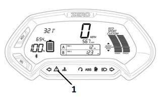
Understanding BMS Flash Code Patterns (Idle Mode)
If a fault has been detected, count the number of times the red indicator light (1) flashes.


Version 1
The numeric error code displayed on the LCD instrument panel provides diagnostics into errors that the Main Bike Board (MBB) has set. These can be useful for troubleshooting issues and determining next steps for solving technical issues.
Retrieving Error Codes
Adjust Button (ADJ): By momentarily pressing or holding the ADJ button (1) you can reset fields and toggle through the trip menus and display options.
Select Button (SEL): By momentarily pressing or holding the SEL button (2) you can reset or select fields in Display A and Display B, change the time, and change the display units.

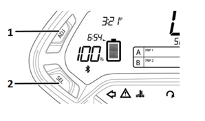
Display A
To select Display A with the dash in its normal operating mode, momentarily press the SEL button once. Press the ADJ button to toggle through the following fields:
• Trip 1 Odometer - Displays individual trip mileage and is reset by pressing and holding the ADJ button for 2 seconds.
Note: Trip 1 is reset each time the battery is recharged to 100%.
• Range - Displays remaining battery power based on learned riding style and usage.
• Error - Displays 2-digit error codes for dealer use.
• RPM - Displays motor RPM.


If an error code has been recorded, it can be retrieved from the dash Display A.


Diagnostic Trouble Code (DTC) List-MBB
Note: If code 57 is retrieved, the motorcycle may only require recharging.
|
DTC
|
Description
|
|
0
|
No Error
|
|
1
|
High Throttle
|
|
2
|
Motor Temperature Warning Stage 1
|
|
3
|
Motor Temperature Warning Stage 2
|
|
4
|
Controller Temperature Warning Stage 1
|
|
5
|
Controller Temperature Warning Stage 2
|
|
6
|
BMS Throttle Enable Wire Error
|
|
7
|
Low Battery Voltage
|
|
8
|
High Battery Temperature Status
|
|
9
|
Low Battery Temperature Status
|
|
10
|
Battery Temperature Warning Stage 1
|
|
11
|
Battery Temperature Warning Stage 2
|
|
12
|
Reserve Partition Warning
|
|
13
|
Reserve Switch Warning
|
|
14
|
Safety Override Active
|
|
15
|
Charger Attached But Not Charging
|
|
16
|
CIB Contactor Compromised
|
|
17
|
Charger Error
|
|
18
|
Battery Temperature Sensor Fault
|
|
19
|
High Charge Current
|
|
20
|
BMS Low Isolation
|
|
21
|
Board Vpack Error
|
|
22
|
Board Temperature Error
|
|
23
|
Post Error
|
|
24
|
Startup Error
|
|
25
|
Contactor Open Warning
|
|
26
|
Contactor Welded Error
|
|
27
|
Precharge Error
|
|
28
|
BMS Isolation Fault
|
|
29
|
BMS Isolation Danger
|
|
30
|
BMS CAN Error
|
|
31
|
Sevcon CAN Error
|
|
32
|
Module Variance Too High
|
|
33
|
Sevcon Error Turn Off
|
|
34
|
Charge Error Turn Off
|
|
35
|
Loopback Error
|
|
36
|
Board 5V Error
|
|
37
|
Board 3.3V Error
|
|
38
|
Idle Turn Off
|
|
39
|
Throttle Out Of Range Disable
|
|
40
|
BMS Throttle Enable Wire Disable
|
|
41
|
Low Battery Voltage Disable
|
|
42
|
High Battery Temperature Status Disable
|
|
43
|
Low Battery Temperature Status Disable
|
|
44
|
Kill Switch Disable
|
|
45
|
Kickstand Switch Disable
|
|
46
|
BMS Charger Connected Disable
|
|
47
|
MBB Charger Connected Disable
|
|
48
|
Sevcon Startup Disable
|
|
49
|
Contactor Open Disable
|
|
50
|
BMS Self Test Error
|
|
51
|
BMS Self Test Warning
|
|
52
|
Reserve Partition Disable
|
|
53
|
BMS Internal Disable
|
|
54
|
BMS Internal Disable Error
|
|
55
|
BMS Internal Fault Error
|
|
56
|
Monolith Not Connected
|
|
57
|
Module Did Not Connect
|
|
58
|
BMS Sensor Warning
|
|
59
|
BMS System Warning
|
|
60
|
Bike Configuration
|
Version 1
Suspension
Description and Operation
The front and rear suspension can be adjusted for sag and damping. For adjustment procedures, refer to Suspension Adjustment.
Front Suspension
The fork assembly contains the triple tree and fork legs (shocks). The triple tree holds the fork legs in place and attaches the fork assembly to the frame.
The shock has two main actions: Compression when the shock gets
compressed, and rebound when the shock returns back to full length.
Compression damping is the adjustment that determines how fast or slow
the fork compresses. Rebound damping is the adjustment that determines
how fast or slow the fork rebounds.
Rear Suspension
The rear suspension is a swingarm with a monoshock design. One end of the swingarm is connected to the frame (pivot end) and the end to the wheel. Controlling the action/movement of the swingarm is the shock.
The shock is a fully adjustable coilover design. The coilover shock contains a spring surrounding it. The spring rate is adjustable and is factory set for a 82 kg (180 lb) rider. The rate is a measure of how much force is required to compress the spring a given distance. The higher the rate, the more force it takes to compress it a given distance, and the less it compresses under a given force.
The shock has two main actions: Compression when the shock gets compressed, and rebound when the shock returns back to full length. Compression damping is the adjustment that determines how fast or slow the shock compresses. Rebound damping is the adjustment that determines how fast or slow the shock rebounds.
Version 1
|
Application
|
Specification
|
|
|
Metric
|
English
|
|
|
Banjo Bolt
|
31 N•m
|
23 lb ft
|
|
Caliper Bleeder Valve
|
7 N•m
|
62 lb in
|
|
Front Brake Caliper Bolts*
|
26 N•m
|
19 lb ft
|
|
Front Brake Rotor Bolt
|
26 N•m
|
19 lb ft
|
|
Rear Axle Shaft Nut*
|
102 N•m
|
75 lb ft
|
|
Rear Brake Caliper Slide Pin*
|
46 N•m
|
34 lb ft
|
|
Rear Brake Rotor Bolts*
|
13 N•m
|
9.5 lb ft
|
|
Front Axle Pinch Bolts*
|
12 N•m
|
9 lb ft
|
|
Seat Bolts
|
22 N•m
|
16 lb ft
|
|
Rear Tank Bolts
|
5 N•m
|
44 lb in
|
|
Front Fairing Screws
|
2 N•m
|
18 lb in
|
|
Front Tank Bolts
|
4 N•m
|
35 lb in
|
|
ABS HCU Bolts
|
6 N•m
|
72 lb in
|
|
Front Fender Bolts DS
|
3 N•m
|
24 lb in
|
|
Front Fender Bolts S/SR
|
11 N•m
|
8 lb ft
|
|
Front Axle Shaft**
|
54 N•m
|
40 lb ft
|
*Use LOCTITE® 242® (or equivalent)
**Use Anti-Seize (or equivalent)
Version 1
|
Causes |
Correction |
| Sticky caliper or caliper pistons | Replace the caliper. |
| Contaminated or improper brake fluid | Flush the brake system and repair the affected brake components. |
| Loose front or rear brake assembly components | Locate and tighten the loose brake components. |
| Brake lever/pedal binding | Repair or replace the brake lever/pedal. |
Version 1
|
Cause |
Correction |
| Linings damaged by abusive use | Replace the brake linings. |
| Poor rotor surface finish | Replace the rotor. |
Version 1
|
Causes |
Correction |
| Worn out brake linings | Replace the brake linings. |
| Incorrect lining material | Replace the brake linings. |
| Contaminated brake linings | Replace the brake linings. |
| Linings damaged by abusive use | Replace the brake linings. |
| Scored rotor | Replace the rotor. |
Version 1
|
Causes |
Correction |
| Loose front or rear suspension parts | Locate and tighten, repair or replace the loose front or rear suspension components. |
| Worn out brake linings | Replace the brake linings. |
| Uneven brake lining material | Replace the brake linings. |
| Contaminated brake linings | Replace the brake linings. |
| Linings damaged by abusive use | Replace the brake linings. |
Scraping Noise
|
Causes |
Correction |
| Loose front suspension parts | Locate and tighten, repair or replace the loose front or rear suspension components. |
|
• Worn out brake linings
|
Replace the brake linings. |
|
• Contaminated brake lining
|
Replace the brake linings. |
|
• Linings damaged by abusive use
|
Replace the brake linings. |
|
• Front or rear brake assembly components loose
|
Locate and tighten the loose brake components. |
Chatter/Roughness
|
Causes |
Correction |
|
• Scored rotor
|
Replace the rotor. Inspect and replace brake linings if necessary. |
|
• Improper thickness variation in rotor
|
Replace the rotor. |
|
• Excessive rotor lateral runout
|
Replace the rotor. |
|
• Loose front or rear brake assembly components
|
Locate and tighten the loose brake components. |
Version 1
|
Causes |
Correction |
| Contaminated or improper brake fluid | Flush the brake system and repair the affected brake components. |
| Sticky caliper or caliper pistons | Replace the caliper. |
Version 1
|
Causes |
Correction |
| Glazed brake linings | Replace the brake linings. |
| Worn out brake linings | Replace the brake linings. |
| Incorrect lining material | Replace the brake linings. |
| Contaminated brake linings | Replace the brake linings. |
| Linings damaged by abusing use | Replace the brake linings. |
| Restricted brake fluid passage | Locate and repair the brake fluid passage restriction. |
| Brake lever/pedal interference or binding | Repair or replace the brake lever/pedal. |
Version 1
|
Causes |
Correction |
| Air in the brake system | Bleed the brake system. |
| Leaking brake hose or connection | Locate and repair the brake hose or the connection. |
| Leaking caliper piston seal | Replace the caliper. |
| Leaking master cylinder (internally) | Replace the master cylinder. |
| Contaminated/improper brake fluid | Flush the brake system and repair the affected brake components. |
| Loose front or rear brake assembly components | Locate and tighten loose brake components. |
Version 1
If a malfunction occurs in the ABS system, the amber ABS warning indicator will turn on during the ignition cycle during which the malfunction is detected.
A diagnostic trouble code will store under the following conditions:
• The malfunction is current
• The malfunction is intermittent
The diagnostic codes are held in the system and require a special cable to connect to it and retrieve the trouble codes.
Diagnostics Trouble Code (DTC) List
TBD
Version 1
The following procedure is used to check the ABS system. This will allow you to read DTC faults, clear DTC faults, read data, and program this system.
1. On a computer with Tera Term installed, connect the USB A-B cable to the computer, and the other end to the C3 OBD-II (data link) connector.
Launching the ABS Scan Tool
1. Power ON the motorcycle.
2. Find this icon on your desktop. Click the icon to start the program.


3. After clicking the icon, the folder below will open. Click on the “PROGRAMMING ROOT” selection.


4. This will open a folder of selectable model years (MY). Select the MY motorcycle you are connected to. NOTE: 2015 is the first year ABS was offered.


5. This will open folders of selectable modules. Click on the ABS folder.


6. This will open up a CAN folder. Click on the folder.


7. This will open up different batch files; the 3 that you will use for the ABS system are:
• ABS_CLEAR_DTCS
• ABS_MENU
• ABS_READ_DTCS


Clearing DTC Codes
1. Click on the ABS_CLEAR_DTCS selection.


2. You may get an Open File – Security Warning. If you do, click the Run button.


3. This will open up a command prompt window with information about clearing the DTC’s.


ABS Check Main Menu
1. Click on the ABS_MENU selection.


2. You may get an Open File – Security Warning. If you do, click the Run button.


3. This will open up a command prompt window with different selections.


At this point you can select from the titles (B) within the command prompt window. By selecting the letter next to the title (A) and typing it in at the curser area (C), the information within that title will display.


Example: If set ABS variant coding is selected (A), the bottom of the command prompt window will display all the information (B) within that title. Note: this window is scrollable using the slide button on the right of the window.


Reading ABS Diagnostic Trouble Codes (DTCS)
1. Click on the ABS_READ_DTCS selection.


2. You may get an Open File – Security Warning. If you do, click the Run button.


3. This will open a command prompt window with information about any DTCs that are set.


Version 1
Brake Pad Inspection
The brake pads must be
inspected when specified in the maintenance schedule. Visually inspect
the brakes by looking at the remaining brake pad material through the
sides of the brake caliper.
Replace the brake pads if either pad’s
thickness is 0.053 in (1.35 mm) or less. If the brake pads are worn,
replace both brake pads immediately.
Brake Disc Inspection
The thickness of the brake discs should be checked
regularly. The minimum thickness is 0.14 in (3.50 mm).
Version 1
| Torque settings for: Brake Pad Replacement-Front | |
| Item | Torque Setting |
| Front Brake Caliper Bolts | 26 N•m (19 lb ft) |
 Show Torque Table
Required Tools
• Flat blade screwdriver
• T25 star socket
• 8mm hex wrench
Fastener Torques
Notice: Refer to Fastener Notice in General Information.
• Front brake caliper bolts* to 26 N•m (19 lb ft)
*Use LOCTITE® 242® (or equivalent)
Removal Procedure
1. Remove the 2 caliper bolts (1).
Support the brake caliper (2) with mechanic's wire, or equivalent, whenever it is separated from its mount, and the hydraulic flexible brake hose is still connected. Failure to support the caliper in this manner will cause the flexible brake hose to bear the weight of the caliper, which may cause damage to the brake hose and in turn may cause a brake fluid leak.
2. Slide the brake caliper off of the brake rotor and support the brake caliper with mechanic's wire or equivalent. DO NOT disconnect the hydraulic brake hose from the brake caliper.

Important: To prevent dirt and other contaminants from entering the master cylinder, thoroughly clean the cover before removal.
3. Remove the two screws to release the cover from the front master cylinder reservoir.
Note: As the pistons are pushed back into the caliper, the fluid level may rise and overflow the reservoir. Watch the fluid level as the pistons are retracted and remove fluid from the reservoir if necessary.
4. Press in the inner and outer brake pads pushing the pistons back into their bores.
5. Remove the caliper slide pin clip (1).
6. Remove the caliper slide pin (2), and remove the brake pads (3) from the caliper.
7. Inspect the brake caliper and brake hardware and replace as needed.

Installation Procedure
1. Install the disc brake pads (3) to the brake caliper, making sure that the anti-rattle clip is in position.
2. Install the caliper slide pin (2) and tighten.
3. Install the caliper slide pin clip (1).

4. Slide the brake caliper onto the rotor, making sure that the disc brake pads are centered on the brake rotor.
Notice: Refer to Fastener Notice in General Information.
5. Install the front caliper bolts (1).
Tighten
Front brake caliper bolts to 26 N•m (19 lb ft)
Caution: After installation of new pads, and before moving motorcycle, pump the front brake lever to build brake system pressure. Insufficient pressure can adversely affect brake performance, which could result in death or serious injury.
6. Verify that the brake fluid level is full. Add DOT 4 brake fluid, if necessary.
7. Install master cylinder reservoir cover.
Caution: After completing repairs or bleeding the system, always test motorcycle brakes at low speed. If brakes are not operating properly or braking efficiency is poor, testing at a high speed could result in death or serious injury.
8. Gently use the brakes a few times at low speeds (less than 25 mph [40 km/h]) to develop proper braking friction. With new brake systems or just new pads, the first few braking applications will result in very little braking power.
9. Road test the motorcycle. Refer to Road Testing Procedure. If the brakes feel spongy, bleed the system.

Version 1
| Torque settings for: Brake Pad Replacement-Rear | |
| Item | Torque Setting |
| Brake Caliper Slide Pin | 46 N•m (34 lb ft) |
 Show Torque Table
Required Tools
• T25 star socket
Fastener Torques
• Brake caliper slide pin* 46 N•m (34 lb ft)
*Use LOCTITE® 242® (or equivalent)
Removal Procedure
Caution: Always replace brake pads in pairs. Never replace just one brake pad. Mismatched brake pads can lead to brake system damage and loss of braking performance, which could result in serious injury or death.
1. Remove the caliper slide pin clip (1).
2. Remove the caliper slide pin (2).
Important: To prevent dirt and other contaminants from entering the master cylinder, thoroughly clean the cover before removal.
3. Remove the brake fluid reservoir cap from the reservoir.
Note: As the piston is pushed back into the caliper, fluid level may rise and overflow the reservoir. Watch the fluid level as the piston is retracted and remove fluid from the reservoir if necessary.
4. Press in the inner and outer brake pads pushing the piston back into the bore.
5. Remove the disc brake pads (3) from the brake caliper.
6. Inspect the brake caliper and brake hardware and replace as needed.

Installation Instructions
1. Install the disc brake pads (3) into the brake caliper, making sure that the anti-rattle clip is in position.
Notice: Refer to Fastener Notice in General Information.
2. Install the caliper slide pin (2).
Tighten
Brake caliper slide pin to 46 N•m (34 lb ft)
3. Install the caliper slide pin clip (1)

Caution: After installation of new pads and before moving motorcycle, pump the rear brake pedal to build brake system pressure. Insufficient pressure can adversely affect brake performance, which could result in death or serious injury.
4. Verify that brake level fluid is full. Add DOT 4 brake fluid, if necessary.
5. Install master cylinder reservoir cap.
Caution: After completing repairs or bleeding the system, always test motorcycle brakes at low speed. If brakes are not operating properly or braking efficiency is poor, testing at a high speed could result in death or serious injury.
6. Gently use the brakes a few times at low speeds (less than 25 mph [40 km/h]) to develop proper braking friction. With new brake systems or just new pads, the first few braking applications will result in very little braking power.
7. Road test the motor cycle; refer to Road Testing Procedure. If the brakes feel spongy, bleed the system.
Version 1
| Torque settings for: Brake Caliper Replacement-Front | |
| Item | Torque Setting |
| Banjo Bolt | 31 N•m (23 lb ft) |
| Caliper Bleeder Valve | 7 N•m (62 lb in) |
 Show Torque Table
Required Tools
• 14mm wrench
• 8mm hex wrench
Fastener Torques
Notice: Refer to Fastener Notice in General Information.
• Banjo bolt 31 N•m (23 lb ft)
• Caliper bleeder valve 7 N•m (62 lb in)
Removal Procedure
1. Remove the brake pads. Refer to Brake Pad Replacement-Front.
Notice: Refer to Brake Fluid Effects on Paint and Electrical Components Notice in General Information.
2. Remove the front brake hose banjo bolt (1) and sealing washers (2) from the caliper JJUAN 32/30MM FRONT CALIPER SDS.
3. Drain the brake fluid into an approved container.

Installation Procedure
Important: Always use new sealing washers on the banjo fittings.
Notice: Refer to Fastener Notice in General Information.
1. Install the front brake hose to the caliper with the banjo bolt (1) and new sealing washers (2).
Tighten
Banjo bolt to 31 N•m (23 lb ft)
2. Install the brake pads. Refer to Brake Pad Replacement-Front.
3. Bleed the front brake system.
4. Road test the motorcycle. Refer to Road Testing Procedure.

Version 1
| Torque settings for: Brake Caliper Replacement-Rear | |
| Item | Torque Setting |
| Banjo Bolt | 31 N•m (23 lb ft) |
| Caliper Bleeder Valve | 7 N•m (62 lb in) |
| Axle Shaft Nut | 102 N•m (75 lb ft) |
| Brake Caliper Slide Pin | 46 N•m (34 lb ft) |
 Show Torque Table
Required Tools
• 27mm socket
• T25 Star socket and socket wrench
• 14mm wrench
Fastener Torques
Notice: Refer to Fastener Notice in General Information.
• Banjo bolt 31 N•m (23 lb ft)
• Caliper bleeder valve 7 N•m (62 lb in)
• Axle shaft nut 102 N•m (75 lb ft)
• Brake caliper slide pin 46 N•m (34 lb ft)
Removal Procedure
1. Remove the brake pads. Refer to Brake Pad Replacement-Rear.
2. Securely raise and support the motorcycle so that the rear wheel is off the ground.
3. Remove the rear axle nut (1) and tap out the axle shaft (2).
Note: Be aware of the axle shaft spacer on the left side of the wheel.

4. Lower the wheel and remove the drive belt from the sprocket.
5. Separate the brake caliper mounting bracket from the swingarm.
Notice: Refer to Brake Fluid Effects on Paint and Electrical Components Notice in General Information.
6. Remove the rear brake hose banjo bolt (1) and sealing washers (2) from the caliper JJUAN 34MM REAR CALIPER.
7. Drain the brake fluid into an approved container.

Installation Procedure
Important: Always use new sealing washers on the banjo fittings.
Notice: Refer to Fastener Notice in General Information.
1. Install the disc brake pads into the brake caliper, making sure that the anti-rattle clip is in position.
2. Install the caliper slide pin (2).
Tighten
Brake caliper slide pin to 46 N•m (34 lb ft)
3. Install the caliper slide pin clip (1).

4. Place the caliper into position on the swingarm.
5. Place the drive belt onto the wheel sprocket, ensure that left wheel spacer and the ABS sensor are in place.
6. Move the wheel into position, ensuring that the brake rotor is centered between the brake pads.
7. Slide the axle shaft (2) through the swingarm and wheel and install the nut (1).
Tighten
Axle shaft nut to 102 N•m (75 lb ft)

8. Install the rear brake hose to the caliper with the banjo bolt (1) and new sealing washers (2).
Tighten
Banjo bolt to 31 N•m (23 lb ft)

9. Bleed the rear brake system.
10. Road test the motorcycle. Refer to Road Testing Procedure.
Version 1
| Torque settings for: Brake Rotor Replacement-Front | |
| Item | Torque Setting |
| Front Rotor Bolts | 26 N•m (19 lb ft) |
| Axle Pinch Bolts | 12 N•m (9 lb ft) |
| Axle Shaft | 54 N•m (40 lb ft) |
 Show Torque Table
Required Tools
• 16mm hex wrench
• 6mm hex wrench
Fastener Torques
Notice: Refer to Fastener Notice in General Information.
• Front rotor bolts 26 N•m (19 lb ft)
• Axle pinch bolts* 12 N•m (9 lb ft)
• Axle shaft** 54 N•m (40 lb ft)
*Use LOCTITE® 242® (or equivalent)
**Use LOCTITE® anti-seize lubricant (or equivalent)
Removal Procedure
1. Remove the front wheel (3.00X17 FRONT CAST WHEEL ASSY SILVER BLACK, 2.50X19 DS FRONT CAST WHEEL ASSY).
• Raise and support the motorcycle.
• Remove the front axle shaft pinch bolts (2) from the right lower fork leg.
• Unscrew the front axle (1) then slide the axle out of the fork.

2. Remove the 5 Allen bolts (1) securing the rotor to the wheel.
3. Remove the front brake rotor (2) from the wheel.

Installation Procedure
Important: Whenever the rotor has been separated from the wheel flange, any rust or contaminants must be cleaned from the wheel flange and the rotor mating surfaces. Failure to do this may result in excessive assembled lateral runout (LRO) of the brake rotor, which could lead to brake pulsation.
1. Inspect the rotor and wheel flange surface for rust or contamination. Remove rust or contamination if necessary. Clean all fastener threads of LOCTITE®, oil, or grease.
2. Install the brake rotor (2) onto the wheel flange; make sure that the countersunk portion of the brake rotor is facing out.
Notice: Refer to Fastener Notice in General information.
3. Apply LOCTITE® 242® to the threaded portion of the rotor bolts (1) and tighten into the flange.
Tighten
Front rotor bolts to 26 N•m (19 lb ft)

4. Install the front wheel.
• Position the wheel onto the motorcycle and ensure that the brake pads are on each side of the brake rotor.
• Position the ABS sensor between the wheel and the left fork tube. The anti-rotation tab (1) must be installed as shown.

Apply Anti-Seize (or equivalent) and slide the front
axle shaft (1) through both fork legs and the wheel, making sure that
the ABS sensor is in place, and tighten.
Tighten
Axle shaft to 26 N•m (19 lb ft)
• Tighten the front axle pinch bolts (2).
Tighten
Axle pinch bolts to 12 N•m (9 lb ft)
5. Road test the motorcycle. Refer to Road Testing Procedure.

Version 1
| Torque settings for: Brake Rotor Replacement-Rear | |
| Item | Torque Setting |
| Rear Axle Shaft Nut | 102 N•m (75 lb ft) |
| Rear Brake Rotor Bolts | 13 N•m (9.5 lb ft) |
 Show Torque Table
Important: Placement of the anti-rotation tab (1) of the ABS sensor is critical. Failure to install the anti-rotation tab in the correct location will cause sensor damage or failure. The anti-rotation tab must be installed outside of the rear brake caliper housing.

Required Tools
• 5mm hex wrench
• 27mm socket and socket wrench
Fastener Torques
• Rear brake rotor bolts 13 N•m (9.5 lb ft)
• Rear axle shaft nut* 102 N•m (75 lb ft)
*Use LOCTITE® 242® (or equivalent)
Removal Procedure
1. Remove the rear wheel.
• Securely raise and support the motorcycle so that the rear wheel is off the ground.
• Remove the rear axle nut (1) and tap out the axle shaft (2). Note: Be aware of the axle shaft spacer on the left side of the wheel.
• Lower the wheel and remove the drive belt from the sprocket.

Important: Support the brake caliper with mechanic's wire, or equivalent, whenever it is separated from its mount and the hydraulic flexible brake hose is still connected. Failure to support the caliper in this manner will cause the flexible brake hose to bear the weight of the caliper, which may cause damage to the brake hose and in turn may cause a brake fluid leak.
2. Move and support the brake caliper with mechanic's wire or equivalent. DO NOT disconnect the hydraulic brake hose from the brake caliper.
3. Remove the 4 Allen bolts (1) securing the rotor to the wheel.
4. Remove the rear brake rotor (2) from the wheel.

Installation Procedure
Important: Whenever the rotor has been separated from the wheel flange, any rust or contaminants must be cleaned from the wheel flange and the rotor mating surfaces. Failure to do this may result in excessive assembled lateral runout (LRO) of the brake rotor, which could lead to brake pulsation.
1. Inspect the rotor and wheel flange surface for rust or contamination. Remove rust or contamination if necessary. Clean all fastener threads of LOCTITE®, oil, or grease.
2. Install the brake rotor (2) onto the wheel flange; make sure that the countersunk portion of the brake rotor is facing out.
Notice: Refer to Fastener Notice in General information.
3. Apply LOCTITE® 242® to the threaded portion of the rotor bolts (1) and tighten into the flange.
Tighten
Rear brake rotor bolts to 13 N•m (9.5 lb ft)

4. Install the rear wheel.
• Place the drive belt onto the wheel sprocket, ensuring that the left wheel spacer is in place.
• Position the wheel onto the motorcycle and ensure that the brake pads are on each side of the brake rotor.
• Position the ABS sensor between the wheel and the rear brake caliper housing. The anti-rotation tab (1) must be installed outside of the rear brake caliper housing.

• Slide the axle shaft (2) through the swingarm and wheel and install the nut (1).
Tighten
Axle shaft nut to 102 N•m (75 lb ft)
5. Road test the motorcycle. Refer to Road Testing Procedure.

Version 1
| Torque settings for: ABS Module Replacement | |
| Item | Torque Setting |
| Seat Bolts | 22 N•m (16 lb ft) |
| Rear Tank Bolts | 5 N•m (48 lb in) |
| Front Fairing Screws | 2 N•m (18 lb in) |
| Front Tank Bolts | 4 N•m (35 lb in) |
| Front Fender Bolts DS | 3 N•m (24 lb in) |
| Front Fender Bolts S/SR | 11 N•m (8 lb ft) |
| Banjo Bolt 31 N•m (23 Lb Ft) | 8 N•m (72 lb in) |
 Show Torque Table
Required Tools
• 3mm hex wrench
• 4mm hex wrench
• 5mm hex wrench
• 14mm wrench
Fastener Torques
Notice: Refer to Fastener Notice in General Information
• Seat bolts 22 N•m (16 lb ft)
• Rear tank bolts 5 N•m (48 lb in)
• Front fairing screws 2 N•m (18 lb in)
• Front tank bolts 4 N•m (35 lb in)
• ABS HCU bolts 8 N•m (72 lb in)
• Banjo bolts 31 N•m (23 lb ft)
• Front fender bolts DS 3 N•m (24 lb in)
• Front fender bolts S/SR/DSR 11 N•m (8 lb ft)
Caution: Mark the orientation and location of all hydraulic brake lines on the ABS Module (HCU) prior to removal. Failure to do so could result in incorrect ABS behavior, such as brake locking.
Removal Procedure
1. Remove the seat.
2. Remove the front fender (PAINTED S/SR FRONT FENDER YELLOW #3, PAINTED S/SR FRONT FENDER WHITE #3, PAINTED S/SR FRONT FENDER BLACK #3, PAINTED S/SR FRONT FENDER RED #3, FRONT FENDER DIRT BRAKE LINE HOLE).
3. Remove the tank assembly (PAINTED S YELLOW POWER TANK ASSEMBLY , PAINTED S WHITE POWER TANK ASSEMBLY , PAINTED S BLACK POWER TANK ASSEMBLY , PAINTED S RED POWER TANK ASSEMBLY , PAINTED DS ORANGE POWER TANK ASSEMBLY , PAINTED DS WHITE POWER TANK ASSEMBLY , PAINTED DS BLACK POWER TANK ASSEMBLY , PAINTED DS GRAPHITE POWER TANK ASSEMBLY , PAINTED SR YELLOW CHARGE TANK ASSEMBLY, PAINTED SR WHITE CHARGE TANK ASSEMBLY , PAINTED SR BLACK CHARGE TANK ASSEMBLY, PAINTED SR RED CHARGE TANK ASSEMBLY , PAINTED S YELLOW CHARGE TANK ASSEMBLY , PAINTED S WHITE CHARGE TANK ASSEMBLY, PAINTED S BLACK CHARGE TANK ASSEMBLY, PAINTED S RED CHARGE TANK ASSEMBLY, PAINTED DS WHITE CHARGE TANK ASSEMBLY , PAINTED DS ORANGE CHARGE TANK ASSEMBLY , PAINTED DS BLACK CHARGE TANK ASSEMBLY, PAINTED DS GRAPHITE CHARGE TANK ASSEMBLY , PAINTED DSR WHITE CHARGE TANK ASSEMBLY, PAINTED DSR ORANGE CHARGE TANK ASSEMBLY, PAINTED DSR BLACK CHARGE TANK ASSEMBLY , PAINTED DSR GRAPHITE CHARGE TANK ASSEMBLY, PAINTED SR YELLOW POWER TANK ASSEMBLY, PAINTED SR WHITE POWER TANK ASSEMBLY , PAINTED SR BLACK POWER TANK ASSEMBLY, PAINTED SR RED POWER TANK ASSEMBLY, PAINTED DSR WHITE POWER TANK ASSEMBLY, PAINTED DSR ORANGE POWER TANK ASSEMBLY, PAINTED DSR BLACK POWER TANK ASSEMBLY, PAINTED DSR GRAPHITE POWER TANK ASSEMBLY, PAINTED S YELLOW TANK TRUNK ASSEMBLY , PAINTED S WHITE TANK TRUNK ASSEMBLY, PAINTED S BLACK TANK TRUNK ASSEMBLY , PAINTED S RED TANK TRUNK ASSEMBLY, PAINTED DS WHITE TANK TRUNK ASSEMBLY , PAINTED DS ORANGE TANK TRUNK ASSEMBLY , PAINTED DS BLACK TANK TRUNK ASSEMBLY , PAINTED DS GRAPHITE TANK TRUNK ASSEMBLY , PAINTED SR YELLOW TANK TRUNK ASSEMBLY, PAINTED SR WHITE TANK TRUNK ASSEMBLY, PAINTED SR BLACK TANK TRUNK ASSEMBLY, PAINTED SR RED TANK TRUNK ASSEMBLY , PAINTED DSR WHITE TANK TRUNK ASSEMBLY , PAINTED DSR ORANGE TANK TRUNK ASSEMBLY, PAINTED DSR BLACK TANK TRUNK ASSEMBLY , PAINTED DSR GRAPHITE TANK TRUNK ASSEMBLY ).
4. Remove the right and left chin fairing panels (SDS CHIN FAIRING LEFT, REWORKED CHIN FAIRING RIGHT, CAM LOCK, SDS CHIN FAIRING RIGHT).
5. Remove the center fairing panel.
6. Move the turn signal flasher out of the way.
Notice: Refer to Brake Fluid Effects on Paint and Electrical Components Notice in General Information.
7. Place a suitable drain pan under the HCU.
8. Disconnect the C428 module harness connector (1).
Caution: Mark the orientation and location of all hydraulic brake lines on the ABS Module (HCU) prior to removal. Failure to do so could result in incorrect ABS behavior, such as brake locking.
9. Remove all brake hose banjo bolts (2) and sealing washers (3) from the HCU.

10. Remove the lower HCU bolt (1).

11. Remove the left side HCU bolt (1) and remove the HCU from the frame.

Installation Procedure
1. Install the HCU onto the frame and install the lower bolt (1).

Notice: Refer to Fastener Notice in General Information.
2. Install the left side bolt (1).
Tighten
ABS HCU bolts to 8 N•m (72 lb in)

Caution: Correct orientation and location of all hydraulic brake lines on the ABS Module (HCU) is crucial. Failure to do so could result in incorrect ABS behavior, such as brake locking.
Important: Always use new sealing washers on the banjo fittings.
3. Install the brake hoses to the module in the same
orientation and location as removed with the banjo bolt (2) and new
sealing washers (3).
Tighten
Banjo bolt 31 N•m (23 lb ft)
4. Connect the C428 module harness connector (1) onto the HCU.

5. Install the center fairing panel.
6. Install the right and left chin fairing panels.
7. Move the turn signal flash back to its original location.
8. Install the tank assembly.
9. Install the seat.
10. Bleed the brake system.
11. Road test the motorcycle. Refer to Road Testing Procedure.
Version 1
| Torque settings for: ABS Sensor Replacement-Front | |
| Item | Torque Setting |
| Brake Caliper Bolt | 26 N•m (19 lb ft) |
| Axle Pinch Bolts | 12 N•m (9 lb ft) |
| Axle Shaft | 54 N•m (40 lb ft) |
 Show Torque Table
Required Tools
• 16mm hex wrench
• 6mm hex wrench
• 3mm hex wrench
Fastener Torques
Notice: Refer to Fastener Notice in General Information.
• Axle pinch bolts* to 12 N•m (9 lb ft)
• Brake caliper bolt 26 N•m (19 lb ft)
• Axle shaft** 54 N•m (40 lb ft)
*Use LOCTITE® 242® (or equivalent)
**Use LOCTITE® anti-seize lubricant (or equivalent)
Removal Procedure
1. Remove the front wheel (3.00X17 FRONT CAST WHEEL ASSY SILVER BLACK, 3.00X17 FRONT CAST WHEEL ASSY SILVER BLACK, 2.50X19 DS FRONT CAST WHEEL ASSY).
• Raise and support the motorcycle.
• Remove the front axle shaft pinch bolts (2) from the right lower fork leg.
• Unscrew the front axle (1) then slide the axle out of the fork.

2. Remove the lower brake caliper bolt (1).

3. Remove the other two remaining harness clips from the fork.
4. Disconnect the C429 harness connector from behind the headlamp.
5. Remove the 3 right front turn signal bolts (1) and move the turn signal housing out enough to slide the ABS harness (2) from the turn signal housing area.
6. Remove the ABS sensor.

Installation Procedure
Notice: Refer to Fastener Notice in General information.
1. Install the front wheel.
• Position the wheel onto the motorcycle and ensure that the brake pads are on each side of the brake rotor.
• Position the ABS sensor between the wheel and the left fork tube. The anti-rotation tab (1) must be installed as shown.

• Apply anti-seize (or equivalent) and slide the front
axle shaft (1) through both fork legs and the wheel, making sure that
the ABS sensor is in place, and tighten.
Tighten
Axle shaft to 54 N•m (40 lb ft)
• Tighten the front axle pinch bolts
Axle shaft pinch bolts to 12 N•m (9 lb ft)

2. Position the ABS sensor harness clamp, and install the lower brake caliper bolt (1).
Tighten
Brake caliper bolt to 26 N•m (19 lb ft)

3. Install the ABS sensor harness into the other two remaining harness clips on the fork.
4. Route the remaining portion of the harness in the same locations as remove and connect the C429 ABS harness connector.
5. Position the ABS sensor grommet (2) and move the turn signal housing into position and install the 3 bolts (1).
6. Road test the motorcycle. Refer to Road Testing Procedure.

Version 1
| Torque settings for: ABS Sensor Replacement-Rear | |
| Item | Torque Setting |
| Axle Shaft Nut | 102 N•m (75 lb ft) |
 Show Torque Table
IMPORTANT: Placement of the anti-rotation tab (1) of the ABS sensor is critical, failure to install the anti-rotation pin in the correct location will cause sensor damage/failure. The anti-rotation tab must be installed outside of the rear brake caliper housing.

Required Tools
• 27mm socket and socket wrench
Fastener Torques
Notice: Refer to Fastener Notice in General Information.
• Axle shaft nut* to 102 N•m (75 lb ft)
*Use LOCTITE® 242® (or equivalent)
Removal Procedure
1. Raise and safely support the motorcycle.
Note: The location of the swingarm ground strap and brake line clips, before removing the inner fender.
2. Remove the 4 bolts securing the rear fender to the swingarm, and remove the (rear inner fender, trimmed rear inner fender).
3. Remove the rear axle nut (1) and tap out the axle shaft (2). Note: Be aware of the axle shaft spacer on the left side of the wheel.

4. Lower the wheel, ensure that the brake caliper housing remains in place on the swingarm.
5. Follow the ABS sensor harness up to the C430 harness connector and disconnect.
6. Remove and harness ties or clips securing the harness on the motorcycle and remove the ABS sensor.
Installation Procedure
1. Ensure that the left wheel spacer is in place and move the wheel into position. Ensure that the brake rotor is centered between the brake pads.
2. Position the ABS sensor between the wheel and the rear brake caliper housing. The anti-rotation tab (1) must be installed outside of the rear brake caliper housing.

3. Slide the axle shaft (2) through the swingarm and wheel and install the nut (1).
Tighten
Axle shaft nut to 102 N•m (75 lb ft)

4. Route the ABS sensor harness connector in the same locations as removed.
5. Connect the C430 ABS sensor harness connector.
6. Install the fender, ground strap and brake line clips onto the swingarm.
7. inspect the routing to ensure that the ABS sensor cable is not in contact with any moving parts.
Version 1
It may be necessary to temporarily disable the Bosch ABS system to further diagnose the hydraulic brake system.
Under normal operation, the ABS dash light will turn on when the
motorcycle is keyed on. The ABS light will remain lit until both wheels
reach 3 mph (5 km/h), at which time the ABS light should turn off. If
the ABS light remains on, there may be an ABS fault, and the rider is
advised that the ABS is NOT active.
To disable the ABS:
1. Ensure motorcycle is at rest on a level, stable surface.
2. Place side (kick) stand in down position.
3. Place motorcycle ignition (kill) switch in OFF position.
4. Turn key switch to ON position.
5. Press and hold the MODE and ADJ buttons on the dash. After four (4) seconds, the ABS light will begin to blink quickly (faster than once per second). Continue holding MODE and ADJ until the ABS light flashes slowly (approximately every 1.2 seconds), and then release.
To reactivate the ABS:
1. Ensure motorcycle is at rest on a level, stable surface.
2. Disconnect the motorcycle from external charge cables.
3. Turn key switch to OFF position.
4. Wait for dash display to turn off completely.
5. Turn key switch to ON position.
6. Resume normal operation.
When the motorcycle is turned off, upon restarting, the ABS will automatically return to its ON setting.
Version 1
Hydraulic Brake System Description and Operation
General Information
Bleed the hydraulic brake system any time a brake hose, master cylinder or brake caliper has been opened or disassembled, or whenever the brake lever operation feels "spongy." Bleeding evacuates air from the system leaving only incompressible hydraulic fluid. This system requires a special bleeding procedure.
Caution: Use only fresh, uncontaminated DOT 4 brake fluid. Fluid containers that have been opened may have been contaminated by dirt or moisture. Use of contaminated brake fluid may adversely affect braking ability and lead to brake failure which could result in death or serious injury.
Notice: Cover adjacent surfaces when removing, draining, filling and/or bleeding brake system components. Spilling brake fluid on painted or other finished surfaces can result in cosmetic damage. Immediately wipe up any spilled brake fluid and thoroughly clean affected area.
System Component Description
The hydraulic brake system consists of the following:
Hydraulic Brake Master Cylinder
• Contains the supply of brake fluid for the hydraulic brake system.
• Converts mechanical input force (brake lever/pedal) into hydraulic output pressure.
The amount of stroke required for this stage will depend of the amount of clearance between the pads and disc.
• Modulation
The brake pads are now clamping the rotor and by stroking the lever further, additional brake power will be generated.
Hydraulic Brake Flexible Hoses
Carry brake fluid to and from hydraulic brake system components.
Hydraulic Brake Wheel Apply Components
Convert hydraulic input pressure into mechanical output force.
System Operation
The front brake is controlled by a hand operated master cylinder located on the right handlebar. The rear brake is controlled by a foot operated master cylinder next to the right foot peg. The master cylinder converts mechanical force into hydraulic pressure. Brake flexible hoses form the hydraulic brake wheel circuits and deliver the hydraulic pressure to the brake calipers. The brake calipers convert the hydraulic pressure into mechanical force which presses linings against rotating brake rotors.
Version 1
Anti-Lock Brake System (ABS) Description and Operation
General Information
Bleed the hydraulic brake system any time a brake hose, ABS module, master cylinder or brake caliper has been opened or disassembled, or whenever the brake lever operation feels "spongy." Bleeding evacuates air from the system leaving only incompressible hydraulic fluid. This system requires a special bleeding procedure.
Caution: Use only fresh, uncontaminated DOT 4 brake fluid. Fluid containers that have been opened may have been contaminated by dirt or moisture. Use of contaminated brake fluid may adversely affect braking ability and lead to brake failure which could result in death or serious injury.
Notice: Cover adjacent surfaces when removing, draining, filling and/or bleeding brake system components. Spilling brake fluid on painted or other finished surfaces can result in cosmetic damage. Immediately wipe up any spilled brake fluid and thoroughly clean affected area.
ABS Major Component Locations

1. ABS Hydraulic Control Unit (HCU)

2. ABS Module Fuse (25 amp)

3. Rear Wheel Speed Sensor

4. Front Wheel Speed Sensor

The Antilock Braking System (ABS) consists of the following components:
• A conventional hydraulic brake system
• Antilock components
The conventional brake system includes the following components:
• A rear master cylinder
• A front master cylinder
• Front disc brake
• Rear disc brake
• Interconnecting hydraulic brake lines
The ABS includes the following components:
• An ABS (Antilock Brake System) Hydraulic Control Unit (HCU)
• Two wheel speed sensors
• The interconnecting wiring
• An amber ABS warning indicator
The ABS HCU controls hydraulic pressure to the following areas:
• The front caliper
• The rear caliper
The ABS HCU controls hydraulic pressure by modulating the hydraulic pressure. This action prevents wheel lock-up.

The HCU constantly monitors the rotational speed of the front and back wheel; if it detects a wheel rotating significantly slower than the other, a condition indicative of impending wheel lock, it actuates the valves to reduce hydraulic pressure to the brake at the affected wheel, thus reducing the braking force on that wheel; the wheel then turns faster. Conversely, if the HCU detects a wheel turning significantly faster than the other, brake hydraulic pressure to the wheel is increased so the braking force is reapplied, slowing down the wheel. This process is repeated continuously.
The HCU is programmed to disregard differences in wheel rotation speed below 5 MPH.
If a fault develops in any part of the ABS, a warning light will illuminated on the instrument panel, and the ABS will be disabled until the fault is corrected.
The diagnostic codes are held in the system and require a special cable to connect to it and retrieve the fault codes.
Version 1
Battery Management System
The Battery Management System (BMS) is located inside the power pack to provide visual notification about the status of the power pack. There are four LED lamps that will flash: One red and three green lamps. The window is covered with a plug (1) located on the front of the power pack (behind the front wheel).

Understanding BMS Flash Code Patterns (Idle Mode)
In this mode, the key is OFF and the power pack is not being charged (the BMS is only monitoring the battery).

Understanding BMS Flash Code Patterns (Charge Mode)
This mode is with the charging cord plugged into the AC power, and the key in the OFF position. During the charging process, first all lights will flash.
Next, lights 1 through 4 will flash depending on the power pack’s state of charge.


Understanding BMS Flash Code Patterns (Run Mode)
In this mode, the key is in the ON position.


Power Pack Empty
If the power pack is completely empty, an error-beep sounds and the BMS disables the throttle. If the Power Pack Empty error-beep still sounds after two hours of charging time, the power pack may need to be repaired or replaced.
Power Pack Full (High Power Pack-Voltage)
If the BMS detects that the power pack is already full, it disables any further charging to prevent damage to the power pack. This is not an error-condition; it is the result of a successful charging cycle. There is no self-test flash code which reports this condition. During an ordinary charging cycle, when the cells are balanced, the charger (not the BMS) senses that the power pack is full and terminates the charging cycle with a “green light.” The BMS does have a redundant back-up mechanism to prevent overcharging of the power pack. If the charger fails to terminate a charging-cycle when the power pack is full, the BMS will terminate charging itself to prevent damage.
Power Pack Too Hot
The power pack contains internal temperature sensors. If the BMS measures excessive internal temperatures, it flashes an error code and disables the throttle. Place the motorcycle in a cool, well-ventilated location and wait a few minutes. If the Too Hot error code still flashes after the power pack has had time to cool down. Your power pack may need to be repaired or replaced.
Power Pack Unbalanced
The power pack contains many individual cells. The BMS continuously monitors the cells and tries to keep them all “in balance” (at the same level-of-charge). If any of the cells are grossly out-of-balance, the BMS flashes a Power Pack Unbalanced error code and disables the throttle. You cannot ride the motorcycle until the problem is resolved. The solution to the problem is to plug in the charger and allow the power pack to charge for 72 hours. This allows the BMS to re-balance the cells in the power pack. If the Power Pack Unbalanced error code still flashes after the power pack has spent more than 72 hours charging. The power pack may need to be repaired or replaced.
Other Error-Flash Patterns
If the BMS in your power pack produces an error code which is not described in Understanding BMS Flash Code Patterns, then the power pack has encountered a serious internal hardware problem.
System Warning Indicator


Understanding BMS Flash Code Patterns (Idle Mode)
If a fault has been detected, count the number of times the red indicator light (1) flashes.


Version 1
The numeric error code displayed on the LCD instrument panel provides diagnostics into errors that the Main Bike Board (MBB) has set. These can be useful for troubleshooting issues and determining next steps for solving technical issues.
Retrieving Error Codes
Adjust Button (ADJ): By momentarily pressing or holding the ADJ button (1) you can reset fields and toggle through the trip menus and display options.
Select Button (SEL): By momentarily pressing or holding the SEL button (2) you can reset or select fields in Display A and Display B, change the time, and change the display units.


Display A
To select Display A with the dash in its normal operating mode, momentarily press the SEL button once. Press the ADJ button to toggle through the following fields:
• Trip 1 Odometer - Displays individual trip mileage and is reset by pressing and holding the ADJ button for 2 seconds.
Note: Trip 1 is reset each time the battery is recharged to 100%.
• Range - Displays remaining battery power based on learned riding style and usage.
• Error - Displays 2-digit error codes for dealer use.
• RPM - Displays motor RPM.


If an error code has been recorded, it can be retrieved from the dash Display A.


Diagnostic Trouble Code (DTC) List-MBB
Note: If code 57 is retrieved, the motorcycle may only require recharging.
|
DTC
|
Description
|
|
0
|
No Error
|
|
1
|
High Throttle
|
|
2
|
Motor Temperature Warning Stage 1
|
|
3
|
Motor Temperature Warning Stage 2
|
|
4
|
Controller Temperature Warning Stage 1
|
|
5
|
Controller Temperature Warning Stage 2
|
|
6
|
BMS Throttle Enable Wire Error
|
|
7
|
Low Battery Voltage
|
|
8
|
High Battery Temperature Status
|
|
9
|
Low Battery Temperature Status
|
|
10
|
Battery Temperature Warning Stage 1
|
|
11
|
Battery Temperature Warning Stage 2
|
|
12
|
Reserve Partition Warning
|
|
13
|
Reserve Switch Warning
|
|
14
|
Safety Override Active
|
|
15
|
Charger Attached But Not Charging
|
|
16
|
CIB Contactor Compromised
|
|
17
|
Charger Error
|
|
18
|
Battery Temperature Sensor Fault
|
|
19
|
High Charge Current
|
|
20
|
BMS Low Isolation
|
|
21
|
Board Vpack Error
|
|
22
|
Board Temperature Error
|
|
23
|
Post Error
|
|
24
|
Startup Error
|
|
25
|
Contactor Open Warning
|
|
26
|
Contactor Welded Error
|
|
27
|
Precharge Error
|
|
28
|
BMS Isolation Fault
|
|
29
|
BMS Isolation Danger
|
|
30
|
BMS CAN Error
|
|
31
|
Sevcon CAN Error
|
|
32
|
Module Variance Too High
|
|
33
|
Sevcon Error Turn Off
|
|
34
|
Charge Error Turn Off
|
|
35
|
Loopback Error
|
|
36
|
Board 5V Error
|
|
37
|
Board 3.3V Error
|
|
38
|
Idle Turn Off
|
|
39
|
Throttle Out Of Range Disable
|
|
40
|
BMS Throttle Enable Wire Disable
|
|
41
|
Low Battery Voltage Disable
|
|
42
|
High Battery Temperature Status Disable
|
|
43
|
Low Battery Temperature Status Disable
|
|
44
|
Kill Switch Disable
|
|
45
|
Kickstand Switch Disable
|
|
46
|
BMS Charger Connected Disable
|
|
47
|
MBB Charger Connected Disable
|
|
48
|
Sevcon Startup Disable
|
|
49
|
Contactor Open Disable
|
|
50
|
BMS Self Test Error
|
|
51
|
BMS Self Test Warning
|
|
52
|
Reserve Partition Disable
|
|
53
|
BMS Internal Disable
|
|
54
|
BMS Internal Disable Error
|
|
55
|
BMS Internal Fault Error
|
|
56
|
Monolith Not Connected
|
|
57
|
Module Did Not Connect
|
|
58
|
BMS Sensor Warning
|
|
59
|
BMS System Warning
|
|
60
|
Bike Configuration
|
Version 1
1. Double click the desktop icon to start the program.


2. If everything is connected properly and the motorcycle is keyed ON, the ZDU program window will open.
3. Select the “Motor Controller Interface” tab at the top of the window.
Buttons Tab
4. Select the “Buttons” tab in the middle of the page. Then select the “Initialize Device” button.

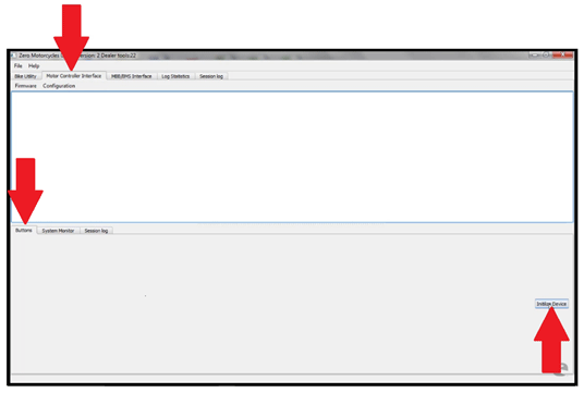
5. Once Initialized, new button selections are available.

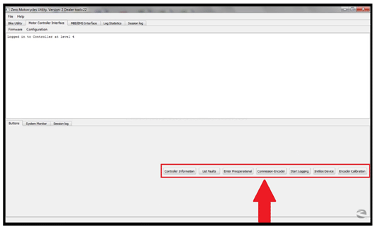
The buttons that we will focus on are as follows:
• Controller Information
Checks the current firmware version installed
• List Faults
Displays any controller fault information
• Commission-Encoder
Before selecting this button, turn the rear wheel one full revolution

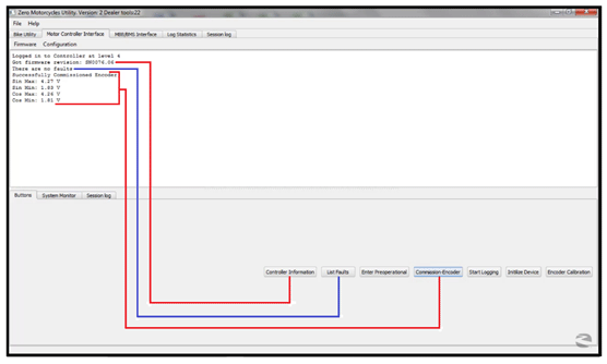
• Encoder Calibration
This is for timing the motor
Important: Ensure the wheel is off the ground!
1. Select the “Encoder Calibration” button and the encoder calibration window will open.
2. If replacing the motor, enter the number, found on the blue tape attached to the motor, to the Encoder Offset field, and press Set Encoder Offset button. If not replacing the motor, go to step 3.
3. Then select the “Start Automated Calibration” button on the encoder calibration window.
4. Then slowly twist the throttle up to about a 1,000 RPM, keeping the dots steady around 10.

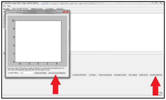
5. The dots will begin to turn from red to blue and automatically adjust the calibration.

6. The calibration is verified by the “Successfully Calibrated Encoder Offset” message. When completed close this window.

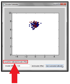
System Monitor Tab
Select this tab to display a live dynamic view of various functions in real time.

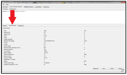
Version 1
This procedure is used to check the firmware revision, pull diagnostic logs, and update individual systems or all systems through one diagnostic port. This greatly reduces the chance of loading non-current firmware, and saves time by going to one location on the motorcycle and one system to perform the update and retrieve the different logs.
The new diagnostic interface is called “Zero Diagnostics Utility” or ZDU. Currently you can run a version check of firmware for all the components (MBB and BMS), and then update them as needed. You can also pull MBB and BMS logs and zip them to a folder for fast emailing to Zero Technical Support for analysis.
1. Double click the desktop icon to start the program.


2. If everything is connected properly and the motorcycle is keyed ON, the ZDU program window will open.
3. With the “Bike Utility” tab selected, press the "Connect To Bike" button. The ZDU will automatically scan available devices for firmware versions.

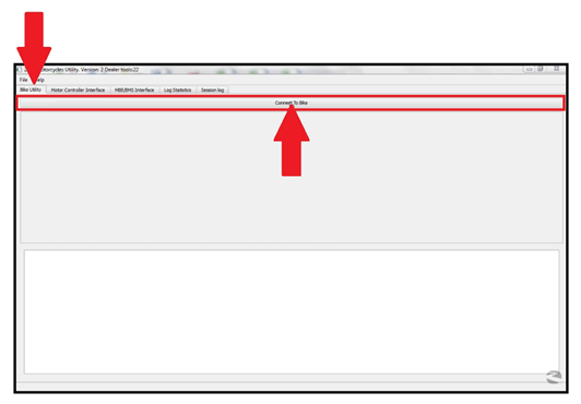
4. Once the scan is complete you will see a summary of devices and firmware versions. If the version number(s) are in red if updates are available.

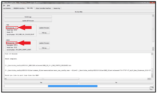
5. Update to the new version, select the “Update Firmware” for an individual devise or “Update All Firmware” for all devises. The newest version of firmware will install and the version number will turn green.

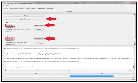
6. You will now be asked if you want to pull logs, use the “Yes” or “No” to select your choice. If you selected “Yes” the firmware will now update. Note: this may take up to 10 minutes to complete.

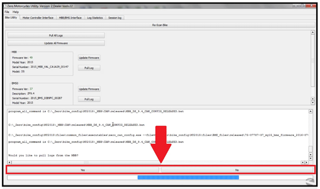
7. When complete select “Re-Scan Bike” to verify that the latest versions have been installed.

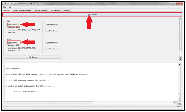
Version 1
This works similar to the tera term.
1. Select the “MBB/BMS Interface” tab at the top of the window then select the “Connect” button at the bottom of the page.

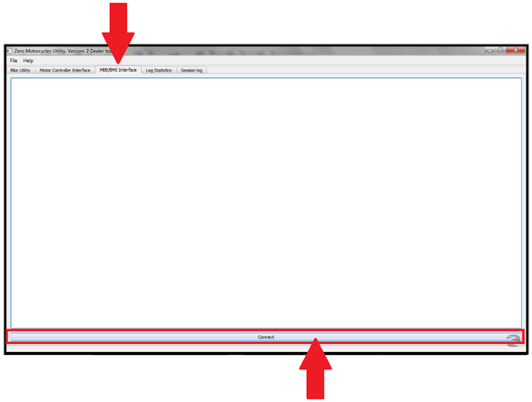
2. Once connected to the motorcycle, type commands in the area at the bottom of the window, then select “Enter”. Type the word “help” will bring up the main menu.

Main Menu Options

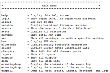
Version 1
